
 Čeština
 Dansk
Dansk Deutsch
 Ελληνικά
 English
 English
 Español
 Suomi
Suomi Français
 Français
 עברית
עברית Hrvatski
 Magyar
 Italiano
 日本語
日本語 한국어
한국어 Nederlands
 Polski
 Português
 Português
 Română
 Русский
 Slovenčina
 Slovenščina
 Svenska
 中文 (中国)

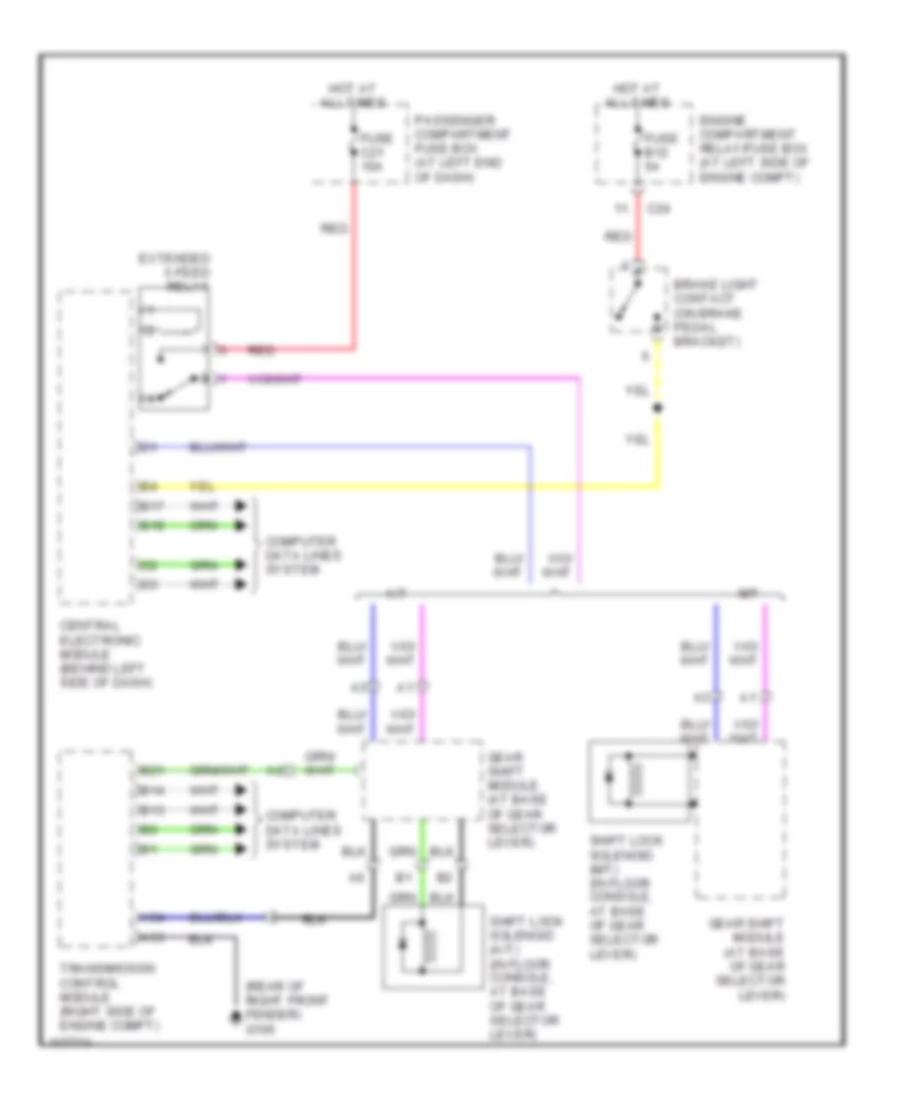
SHIFT INTERLOCKS
Shift Interlock Wiring Diagram for Volvo S80 2001
List of elements for Shift Interlock Wiring Diagram for Volvo S80 2001:

ANTI-LOCK BRAKESBODY COMPUTERANTI-THEFTAIR CONDITIONINGCRUISE CONTROLDEFOGGERSCOMPUTER DATA LINESELECTRONIC POWER STEERINGCOOLING FANGROUND DISTRIBUTIONHEADLIGHTSENGINE PERFORMANCEINTERIOR LIGHTSNAVIGATIONEXTERIOR LIGHTSMEMORY SYSTEMSHORNPOWER DISTRIBUTIONINSTRUMENT CLUSTERRADIOPOWER WINDOWSPOWER MIRRORSPOWER DOOR LOCKSPOWER TOP/SUNROOFPOWER SEATSSUPPLEMENTAL RESTRAINTSTRANSMISSIONWARNING SYSTEMSSTARTING/CHARGINGSHIFT INTERLOCKSWIPER/WASHER