STARTING/CHARGING
Charging Wiring Diagram for Buick Allure CXL 2007
 https://portal-diagnostov.com/license.html
Automotive Electricians Portal FZCO
Automotive Electricians Portal FZCO
https://portal-diagnostov.com/license.html
https://portal-diagnostov.com/license.html
Automotive Electricians Portal FZCO
Automotive Electricians Portal FZCO
List of elements for Charging Wiring Diagram for Buick Allure CXL 2007:
- (in i/p wiring harness, left side of dash, approximately 21 cm from lamp assembly switch towards engine compt pass-thru)
- (not used) a
- 3.6l
- 3.8l
- Batt +
- Battery
- Battery current sensor
- Body control module (bcm) (behind left side of dash, left of steering column)
- Charge indicator
- Clstr fuse 10a
- Computer data lines system
- Current sensor low ref
- Current sensor sig
- Ecm class 2 serial data
- Engine control module (ecm) (top of engine)
- G102 (3.6l: below right front strut tower, 3.8l: near battery)
- G111 (3.6l: lower left front of engine, on transmission stud, near starter, 3.8l: lower left side of engine)
- G202 (left side of dash, at base of steering column)
- Generator
- Generator field duty cycle sig
- Generator turn on sig
- Gnd
- Ground
- Hot at all times
- I/p class 2 serial data
- I/p dimming voltage ref
- I/p fuse block (behind right side of dash)
- Instrument panel cluster (ipc)
- Interior lights system
- Logic
- Pcm class 2 serial data
- Pcm/ecm class 2 serial data
- Power distribution system
- Powertrain control module (pcm)
- Red
- S204
- S211
- Splice pack sp205 (clipped to knee bolster panel, right of data link connector)
- Starter
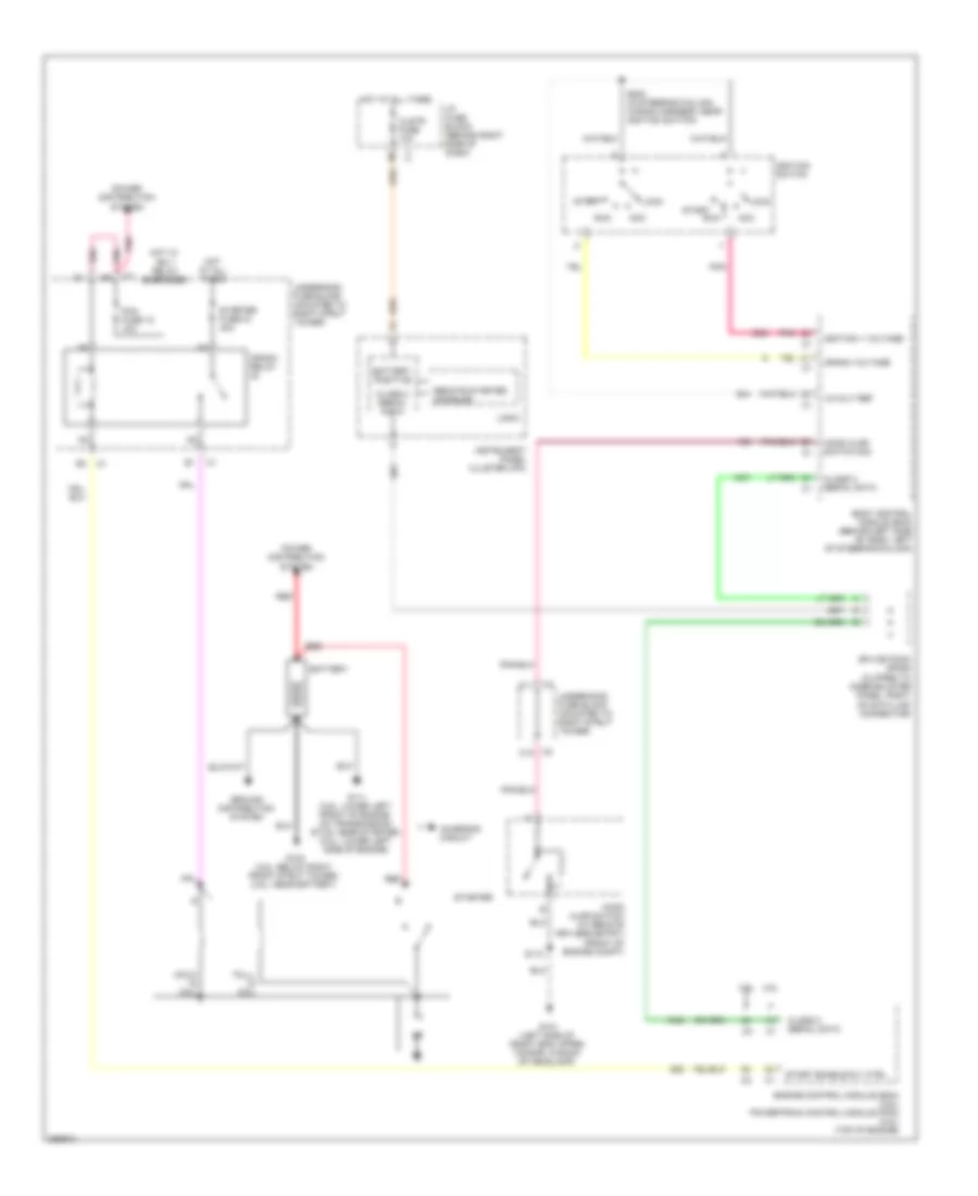
Starting Wiring Diagram for Buick Allure CXL 2007
List of elements for Starting Wiring Diagram for Buick Allure CXL 2007:
- 12-volt ref
- 3.6l
- 3.8l
- Acc
- Battery
- Battery positive
- Body control module (bcm) (behind left side of dash, left of steering column)
- C11
- C12
- Charging circuit
- Class 2 serial data
- Clstr fuse 10a
- Crank relay
- Crank voltage
- Engine control module (ecm) (3.6l) powertrain control module (pcm) (3.8l) (top of engine)
- G101 (left side of front end upper tie bar, in back of headlamp)
- G102 (3.6l: below right front strut tower) (3.8l: near battery)
- G111 (3.6l: lower left front of engine, on transmission stud, near starter) (3.8l: lower left side of engine)
- Ground distribution system
- Hold- in coil
- Hood ajar switch (w/ remote keyless entry) (front of engine compt)
- Hood ajar switch sig
- Hot at all times
- Hot w/ ign 1 relay energized
- I/p fuse block (behind right side of dash)
- Ignition 1 voltage
- Ignition switch
- Instrument panel cluster (ipc)
- Lock
- Logic
- Pcm fuse 15 10a
- Pnk
- Power distribution system
- Pull- in coil
- Red
- Remote starter disabled
- Run
- S112
- S200 (in steering column wiring harness, near ignition switch)
- Splice pack sp205 (clipped to knee bolster panel, right of data link connector)
- Start
- Start enable rly ctrl
- Starter
- Starter fuse 33 40a
- Underhood fuse block (mounted to right strut tower)

 Čeština
 Dansk
Dansk Deutsch
 Ελληνικά
 English
 Español
 Suomi
Suomi Français
 Français
 עברית
עברית Hrvatski
 Magyar
 Italiano
 日本語
日本語 한국어
한국어 Nederlands
 Polski
 Português
 Português
 Română
 Русский
 Slovenčina
 Slovenščina
 Svenska
 Türkçe
 中文 (中国)