STARTING/CHARGING
Charging Wiring Diagram for Chevrolet Malibu LS 2011
 https://portal-diagnostov.com/license.html
Automotive Electricians Portal FZCO
Automotive Electricians Portal FZCO
https://portal-diagnostov.com/license.html
https://portal-diagnostov.com/license.html
Automotive Electricians Portal FZCO
Automotive Electricians Portal FZCO
List of elements for Charging Wiring Diagram for Chevrolet Malibu LS 2011:
- (left side of engine compartment)
- 2.4l (vin b)
- 3.6l
- Batt
- Batt sense fuse 54 5a
- Battery
- Battery current sensor (under battery)
- Body control module (bcm) (under center console)
- Charge ind
- Cluster/ theft fuse 10a
- Computer data lines system
- Current sensor low ref
- Current sensor signal
- D12
- Data bus +
- Data bus -
- Engine control module (ecm) (left front of engine compt)
- Fusible link bu
- G104 (left front corner of engine compt)
- G105
- G109 (left front corner of engine compt)
- Generator
- Generator field duty cycle sig
- Generator turn on sig
- Gnd
- High speed gmlan serial data bus +
- High speed gmlan serial data bus -
- Hot at all times
- Ibcm 1 fuse 30a
- Ign
- Instrument panel cluster (ipc)
- Logic
- Low ref
- Pnk
- Power distribution system
- Red
- Sens sig
- Serial data
- Starter motor
- Tan
- Underhood fuse block
- Volt
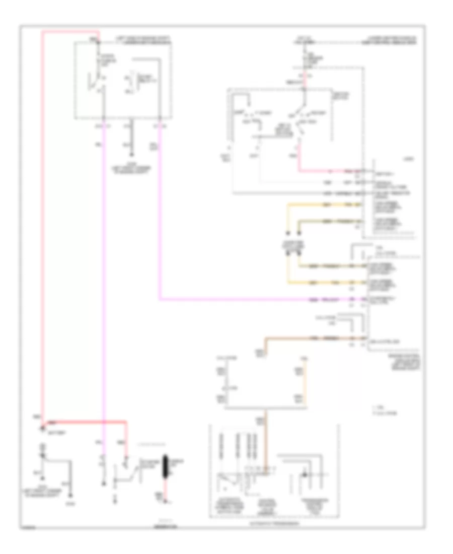
Starting Wiring Diagram for Chevrolet Malibu LS 2011
List of elements for Starting Wiring Diagram for Chevrolet Malibu LS 2011:
- (left side of engine compt)
- (under center console)
- 2.4l (vin b)
- 3.6l
- Acc
- Automatic transmission
- Automatic transmission internal mode switch (ims)
- Battery
- Body control module (bcm)
- C1 x2
- C10
- Computer data lines system
- Control solenoid valve assembly
- D1 x4
- D12 x1
- Engine control module (ecm) (left front of engine compt)
- Fusible link bu
- G104 (left front corner of engine compt)
- G105
- G109 (left front corner of engine compt)
- Generator
- High speed gmlan serial data bus +
- High speed gmlan serial data bus -
- Hot at all times
- Ign key resistor signal
- Ign lk ctrl sig
- Ign sensor fuse 2a
- Ignition 1
- Ignition switch
- Key in ignition switch
- Logic
- Off
- Off/run/ crank voltage
- Pnk
- Red
- Run
- Start
- Start relay 31
- Starter motor
- Starter rly coil ctrl
- Strtr fuse 26 30a
- Tan
- Transmission control module (tcm)
- Underhood fuse block
- X108 e

 Čeština
 Dansk
Dansk Deutsch
 Ελληνικά
 English
 Español
 Suomi
Suomi Français
 Français
 עברית
עברית Hrvatski
 Magyar
 Italiano
 日本語
日本語 한국어
한국어 Nederlands
 Polski
 Português
 Português
 Română
 Русский
 Slovenčina
 Slovenščina
 Svenska
 Türkçe
 中文 (中国)