STARTING/CHARGING
Charging Wiring Diagram for Chevrolet Malibu Maxx LS 2006
 https://portal-diagnostov.com/license.html
Automotive Electricians Portal FZCO
Automotive Electricians Portal FZCO
https://portal-diagnostov.com/license.html
https://portal-diagnostov.com/license.html
Automotive Electricians Portal FZCO
Automotive Electricians Portal FZCO
List of elements for Charging Wiring Diagram for Chevrolet Malibu Maxx LS 2006:
- (2.2l & 3.9l)
- (ecm/ pcm)
- 2.2l
- 3.5l & 3.9l
- 3.5l 2.2l
- 3.9l
- Battery
- Charge indicator
- Class 2 serial data
- Computer data lines system
- G104 (left side of engine compt)
- G105 (3.5l: right rear of engine, on engine to transmission stud)
- Generator
- Generator field duty cycle signal
- Generator turn on signal
- High speed gmlan serial data bus +
- High speed gmlan serial data bus -
- Ign
- Instrument panel cluster (ipc)
- Low speed gmlan serial data
- Power distribution system
- Powertrain control module (pcm) (3.5l & 2.2l) engine control module (ecm) (3.9l) (3.5l & 2.2l: front of battery)
- Red
- Starter solenoid
- Tan
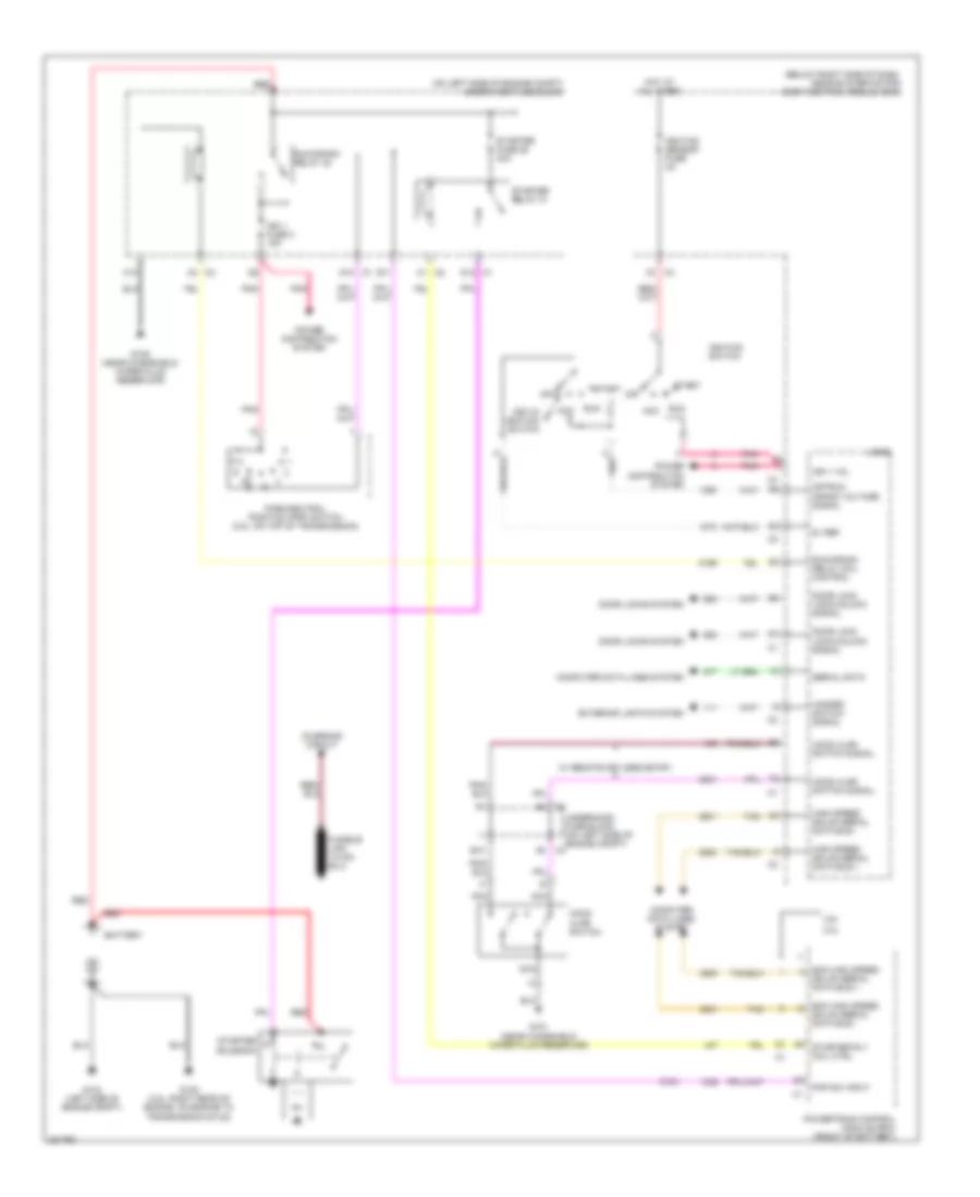
2.2L VIN F
2.2L VIN F, Starting Wiring Diagram for Chevrolet Malibu Maxx LS 2006
List of elements for 2.2L VIN F, Starting Wiring Diagram for Chevrolet Malibu Maxx LS 2006:
- (2.2l)
- (below right side of dash, near blower motor) body control module (bcm)
- (on left side of engine compt) underhood fuse block
- 2.2l
- 3.5l
- 5v ref
- A3 c2
- Acc
- B10
- Battery
- C1 c2
- C10
- C4 d1
- Charging circuit
- Computer data lines system
- D10 c1
- D12 c1
- Door lock lock/unlock signal
- Door locks system
- E11
- Ecm high speed gmlan serial data bus +
- Ecm high speed gmlan serial data bus -
- Exterior lights system
- G101 (near windshield wiper fluid reservoir)
- G104 (left side of engine compt)
- G105 (3.5l: right rear of engine, on engine to transmission stud)
- G109 (near windshield wiper fluid reservoir)
- Hazard switch signal
- High speed gmlan serial data bus +
- High speed gmlan serial data bus -
- Hood ajar switch
- Hood ajar switch signal
- Hot at all times
- Ign 1 fuse 3 15a
- Ign 1 vol
- Ignition sensor fuse 2a
- Ignition switch
- Key-in ignition switch
- Logic
- Nca
- Off
- Off/run crank voltage signal
- Park/neutral position (pnp) switch (3.5l: on top of transmission)
- Pnk
- Pnp sw input
- Power distribution system
- Powertrain control module (pcm) (front of battery)
- Red
- Run
- Run/crank relay 32
- Run/crank relay coil control
- Serial data
- Start
- Starter fuse 26 30a
- Starter relay 31
- Starter rly coil ctrl
- Starter solenoid
- Tan
- Underhood fuse block (on left side of engine compt)
- W/ remote keyless entry
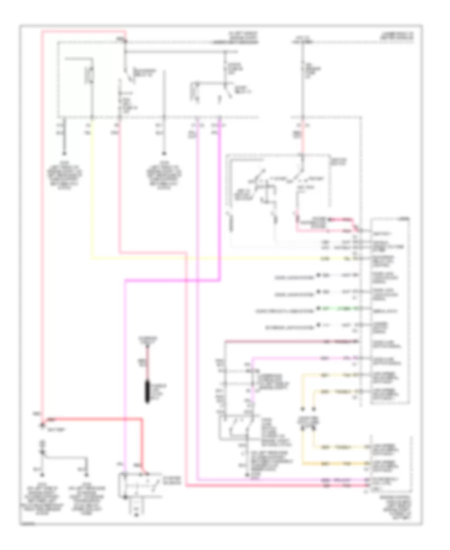
3.5L VIN 8
3.5L VIN 8, Starting Wiring Diagram for Chevrolet Malibu Maxx LS 2006
List of elements for 3.5L VIN 8, Starting Wiring Diagram for Chevrolet Malibu Maxx LS 2006:
- (2.2l)
- (below right side of dash, near blower motor) body control module (bcm)
- (on left side of engine compt) underhood fuse block
- 2.2l
- 3.5l
- 5v ref
- A3 c2
- Acc
- B10
- Battery
- C1 c2
- C10
- C4 d1
- Charging circuit
- Computer data lines system
- D10 c1
- D12 c1
- Door lock lock/unlock signal
- Door locks system
- E11
- Ecm high speed gmlan serial data bus +
- Ecm high speed gmlan serial data bus -
- Exterior lights system
- G101 (near windshield wiper fluid reservoir)
- G104 (left side of engine compt)
- G105 (3.5l: right rear of engine, on engine to transmission stud)
- G109 (near windshield wiper fluid reservoir)
- Hazard switch signal
- High speed gmlan serial data bus +
- High speed gmlan serial data bus -
- Hood ajar switch
- Hood ajar switch signal
- Hot at all times
- Ign 1 fuse 3 15a
- Ign 1 vol
- Ignition sensor fuse 2a
- Ignition switch
- Key-in ignition switch
- Logic
- Nca
- Off
- Off/run crank voltage signal
- Park/neutral position (pnp) switch (3.5l: on top of transmission)
- Pnk
- Pnp sw input
- Power distribution system
- Powertrain control module (pcm) (front of battery)
- Red
- Run
- Run/crank relay 32
- Run/crank relay coil control
- Serial data
- Start
- Starter fuse 26 30a
- Starter relay 31
- Starter rly coil ctrl
- Starter solenoid
- Tan
- Underhood fuse block (on left side of engine compt)
- W/ remote keyless entry
3.9L VIN 1
3.9L VIN 1, Starting Wiring Diagram for Chevrolet Malibu Maxx LS 2006
List of elements for 3.9L VIN 1, Starting Wiring Diagram for Chevrolet Malibu Maxx LS 2006:
- (in left side of engine compt)
- (on left rear side of core support, between windshield washer fluid reservoir & g109) g101
- (under front of center console)
- Acc
- B10
- Battery
- C1 c2
- C10
- Charging circuit
- Computer data lines system
- D1 c4
- D12 c1
- Door lock lock/unlock signal
- Door locks system
- E11
- Engine control module (ecm) (left side of engine compt, in front of battery)
- Exterior lights system
- G104 (on left side of engine compt, on core support, between left inflatable restraint front end sensor & g109)
- G105 (on left rear side of engine compt, on engine transmission stud, below upper coolant hose)
- G109 (left front of engine compt, on left rear side of core support, between g101 & g104)
- Hazard switch signal
- High speed gmlan serial data bus +
- High speed gmlan serial data bus -
- Hood ajar switch (w/ rke) (in front of engine compt, on hood latch)
- Hood ajar switch signal
- Hot at all times
- Ign 1
- Ign sensor fuse 2a
- Ignition 1
- Ignition switch
- Key in ignition switch
- Logic
- Nca
- Off
- Off/run crank voltage 5v ref
- Pcm ign 1 fuse 16 10a
- Pnk
- Power distribution system
- Red
- Run
- Run/crank relay 32
- Run/crank relay coil control
- Serial data
- Start
- Start relay 31
- Starter rly coil ctrl
- Starter solenoid
- Strtr fuse 26 30a
- Tan
- Underhood fuse block
- Underhood fuse block (in left side of engine compt)

 Čeština
 Dansk
Dansk Deutsch
 Ελληνικά
 English
 Español
 Suomi
Suomi Français
 Français
 עברית
עברית Hrvatski
 Magyar
 Italiano
 日本語
日本語 한국어
한국어 Nederlands
 Polski
 Português
 Português
 Română
 Русский
 Slovenčina
 Slovenščina
 Svenska
 Türkçe
 中文 (中国)