STARTING/CHARGING
Charging Wiring Diagram for Ford Aspire 1997
 https://portal-diagnostov.com/license.html
Automotive Electricians Portal FZCO
Automotive Electricians Portal FZCO
https://portal-diagnostov.com/license.html
https://portal-diagnostov.com/license.html
Automotive Electricians Portal FZCO
Automotive Electricians Portal FZCO
List of elements for Charging Wiring Diagram for Ford Aspire 1997:
- (top left front of engine) g110
- Battery
- C209
- C210
- Charge indicator
- Dash fuse box (left side of i/p)
- Engine compartment fuse box (left side of engine compartment)
- Generator/ voltage regulator (right front of engine)
- Head fuse 30a
- Hot in start or run
- Instrument cluster
- Main fuse 80a
- Meter fuse 15a
- Red
- S112
- S114
- S202
- Starter motor/ solenoid (lower right front of engine)
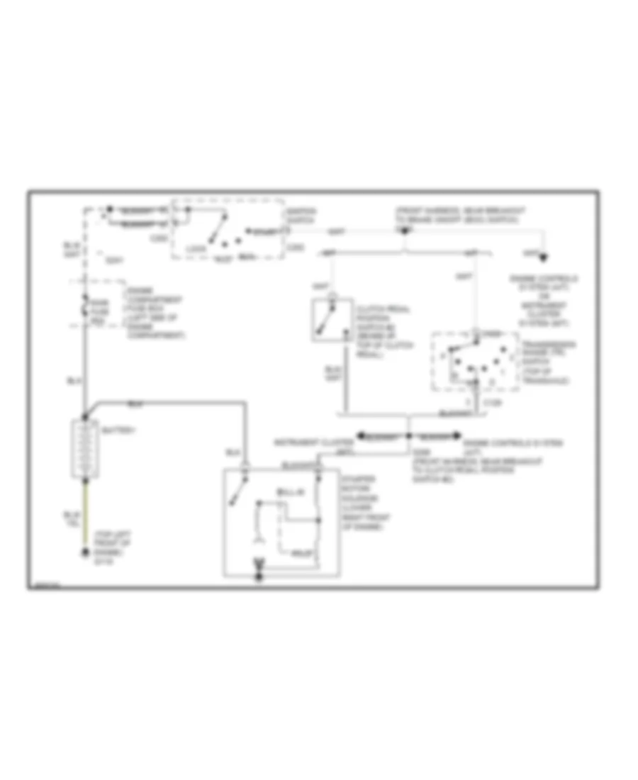
Starting Wiring Diagram for Ford Aspire 1997
List of elements for Starting Wiring Diagram for Ford Aspire 1997:
- (front harness, near breakout to brake on/off (boo) switch) s205
- (top left front of engine) g110
- A/t
- Acc
- Battery
- C129
- C202
- Clutch pedal position switch #2 (behind i/p, top of clutch pedal)
- Engine compartment fuse box (left side of engine compartment)
- Engine controls system (a/t)
- Engine controls system (a/t) or instrument cluster system (m/t)
- Hold
- Ignition switch
- Instrument cluster (m/t)
- Lock
- M/t
- Main fuse 80a
- Pull-in
- Run
- S206 (front harness, near breakout to clutch pedal position switch #2)
- S241
- Start
- Starter motor/ solenoid (lower right front of engine)
- Transmission range (tr) switch (top of transaxle)
 Čeština
 Dansk
Dansk Deutsch
 Ελληνικά
 English
 English
 Español
 Suomi
Suomi Français
 עברית
עברית Hrvatski
 Magyar
 Italiano
 日本語
日本語 한국어
한국어 Nederlands
 Polski
 Português
 Português
 Română
 Русский
 Slovenčina
 Slovenščina
 Svenska
 Türkçe
 中文 (中国)
 Français