STARTING/CHARGING
Charging Wiring Diagram for Ford Expedition 1997
 https://portal-diagnostov.com/license.html
Automotive Electricians Portal FZCO
Automotive Electricians Portal FZCO
https://portal-diagnostov.com/license.html
https://portal-diagnostov.com/license.html
Automotive Electricians Portal FZCO
Automotive Electricians Portal FZCO
List of elements for Charging Wiring Diagram for Ford Expedition 1997:
- 175a
- 20a
- Battery
- C166
- C176
- C177
- C178
- C238
- C243
- Charge indicator
- Fuse 10a
- G123 (rear of engine compt, right side of cowl panel)
- G133 (on engine)
- Generator/ voltage regulator
- Hot in start or run
- Inline mini fuse (near gener- ator)
- Instru- ment cluster
- Junction box fuse/ relay panel
- Mega fuse (alter- nator) (right rear of engine compt)
- Ohms
- Power distribution system
- Red
- Starter motor
- Starter motor relay (right rear of engine compt)
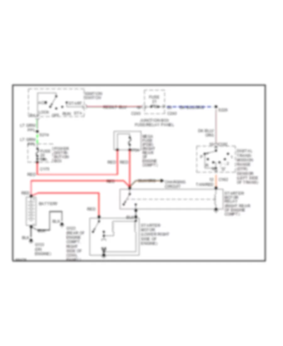
Starting Wiring Diagram for Ford Expedition 1997
List of elements for Starting Wiring Diagram for Ford Expedition 1997:
- 175a
- Acc
- Battery
- C175
- C182
- C243
- Charging circuit
- Digital trans- mission range (dtr) sensor (left side of trans)
- Fuse 15a
- Fuse 50a
- G123 (rear of engine compt, right side of cowl panel)
- G133 (on engine)
- Ignition switch
- Junction box fuse/relay panel
- Lock b4
- Mega fuse (pdb) (right rear of engine compt)
- Off
- Power distri- bution box
- Red
- Run
- S214
- S226
- Sta
- Start
- Starter motor (lower right side of engine)
- Starter motor relay (right rear of engine compt)
- Tan/red

 Čeština
 Dansk
Dansk Deutsch
 Ελληνικά
 English
 Español
 Suomi
Suomi Français
 Français
 עברית
עברית Hrvatski
 Magyar
 Italiano
 日本語
日本語 한국어
한국어 Nederlands
 Polski
 Português
 Português
 Română
 Русский
 Slovenčina
 Slovenščina
 Svenska
 Türkçe
 中文 (中国)