STARTING/CHARGING
Charging Wiring Diagram for Ford Focus SES 2008
 https://portal-diagnostov.com/license.html
Automotive Electricians Portal FZCO
Automotive Electricians Portal FZCO
https://portal-diagnostov.com/license.html
https://portal-diagnostov.com/license.html
Automotive Electricians Portal FZCO
Automotive Electricians Portal FZCO
List of elements for Charging Wiring Diagram for Ford Focus SES 2008:
- Battery
- Battery junction box (bjb) (left rear corner of engine compt)
- C102a
- C1035a
- C1035b
- C175b
- Can+
- Can-
- Cdc10
- Cdc15
- Charge ind
- Computer data lines system
- Fuse 6 15a
- G104 (at left front strut tower)
- G105 (center of engine compt)
- Gencom
- Generator
- Genmon
- Powertrain control module (pcm) (at rear of engine assembly)
- Red
- Starting circuit
- Vdb04
- Vdb05
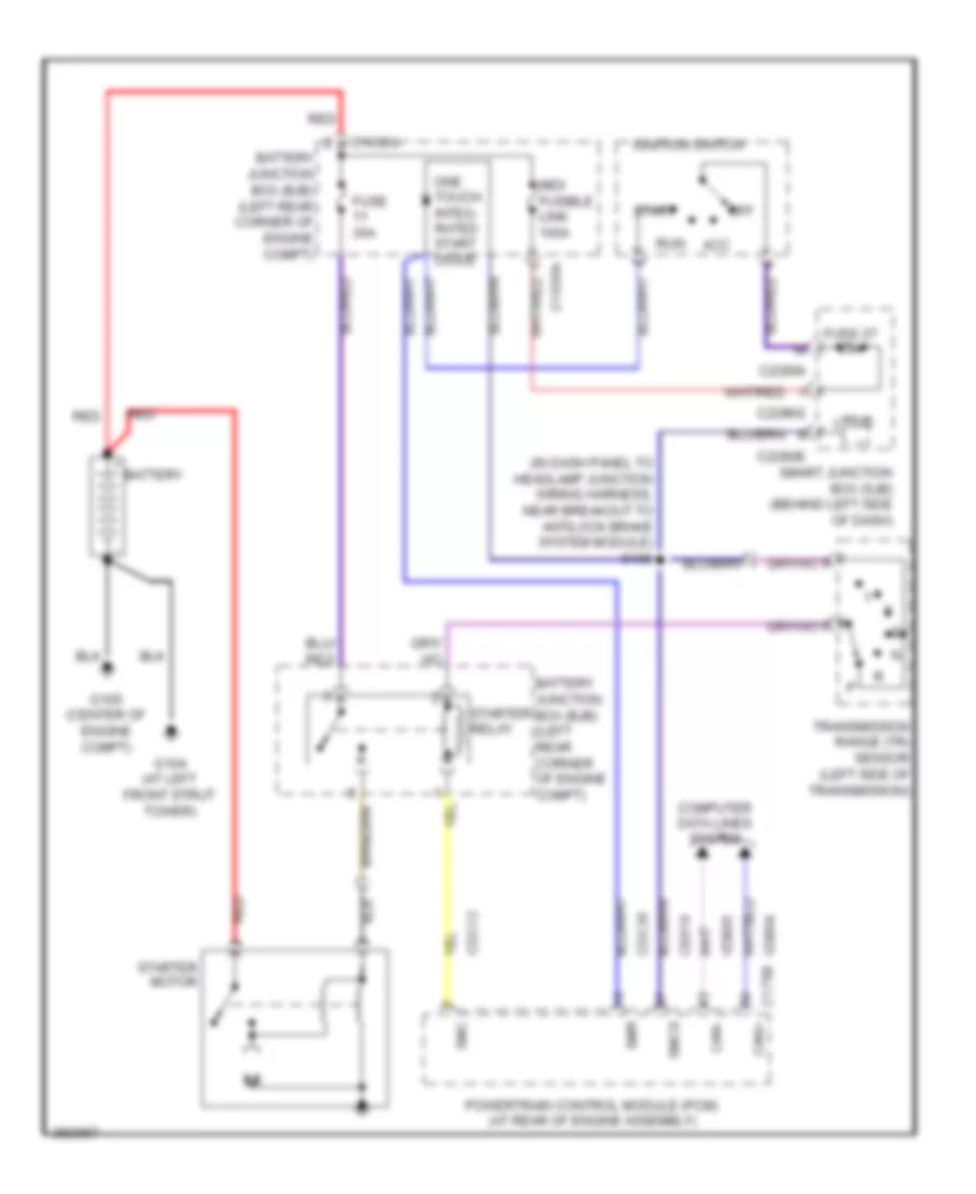
Starting Wiring Diagram, A/T for Ford Focus SES 2008
List of elements for Starting Wiring Diagram, A/T for Ford Focus SES 2008:
- (in dash panel to headlamp junction wiring harness, near breakout to antilock brake system module) s108
- Acc
- Battery
- Battery junction box (bjb) (left rear corner of engine compt)
- C1035a
- C175b can+
- C2280a
- C2280e
- C2280g
- Can-
- Cdc12
- Cdc35
- Ce619
- Computer data lines system
- Fuse 27 20a
- Fuse 30a
- G104 (at left front strut tower)
- G105 (center of engine compt)
- Ignition switch
- Logic
- Midi fusible link 100a
- Off
- One touch integ- rated start diode
- Powertrain control module (pcm) (at rear of engine assembly)
- Red
- Run
- Smart junction box (sjb) (behind left side of dash)
- Smc
- Smcs
- Smr
- Start
- Starter motor
- Starter relay
- Transmission range (tr) sensor (left side of transmission)
- Vdb04
- Vdb05
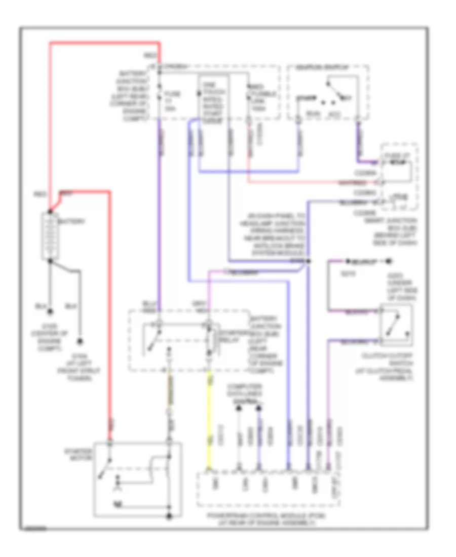
Starting Wiring Diagram, M/T for Ford Focus SES 2008
List of elements for Starting Wiring Diagram, M/T for Ford Focus SES 2008:
- (in dash panel to headlamp junction wiring harness, near breakout to antilock brake system module) s108
- Acc
- Battery
- Battery junction box (bjb) (left rear corner of engine compt)
- C1035a
- C175b smcs
- C175t cpp-bt
- C2280a
- C2280e
- C2280g
- Can+
- Can-
- Cdc12
- Cdc35
- Ce619
- Ce903
- Clutch cutoff switch (at clutch pedal assembly)
- Computer data lines system
- Fuse 27 20a
- Fuse 30a
- G104 (at left front strut tower)
- G105 (center of engine compt)
- G203 (under left side of dash)
- Ignition switch
- Logic
- Midi fusible link 100a
- Off
- One touch integ- rated start diode
- Powertrain control module (pcm) (at rear of engine assembly)
- Red
- Run
- S215
- Smart junction box (sjb) (behind left side of dash)
- Smc
- Smr
- Start
- Starter motor
- Starter relay
- Vdb04
- Vdb05

 Čeština
 Dansk
Dansk Deutsch
 Ελληνικά
 English
 Español
 Suomi
Suomi Français
 Français
 עברית
עברית Hrvatski
 Magyar
 Italiano
 日本語
日本語 한국어
한국어 Nederlands
 Polski
 Português
 Português
 Română
 Русский
 Slovenčina
 Slovenščina
 Svenska
 Türkçe
 中文 (中国)