AUTOMOTIVE ELECTRICIANS PORTAL

STARTING/CHARGING – Honda Pilot EX 2014 – SYSTEM WIRING DIAGRAMS

STARTING/CHARGING

Charging Wiring Diagram for Honda Pilot EX 2014

Charging Wiring Diagram for Honda Pilot EX 2014 https://portal-diagnostov.com/license.html
https://portal-diagnostov.com/license.html Automotive Electricians Portal FZCO Automotive Electricians Portal FZCO
Download PDF file

List of elements for Charging Wiring Diagram for Honda Pilot EX 2014:

  • 120a
  • 5v stabilizer circuit/controller area network controller
  • A10
  • A48
  • A49
  • Alt c sig
  • Alt fr sig
  • Alt l sig
  • Alternator
  • Battery
  • C102
  • C42
  • C43
  • C44
  • Canh
  • Canl
  • Charging system indicator
  • Computer data lines system
  • Drive circuit indicator
  • E27
  • Eld unit
  • Eld unit input
  • Fast controller area network transceiver
  • Fuse 10 7.5a
  • Fuse 10a
  • Fuse 3 10a
  • G1 (left front of engine compt)
  • G202 (right side of engine compt)
  • Gauge control module
  • Hot at all times
  • Hot in on or start
  • Ig1
  • J/c c114 (right front of engine)
  • Meter
  • Micu
  • Multi- fuse 1
  • P10
  • Pcm (right side of engine compt)
  • Pnk
  • Power distribution system
  • Red
  • Starting circuit
  • T101
  • Tan
  • Under-dash fuse/relay box (left end of dash)
  • Under-hood fuse/relay box (right rear of engine compt)

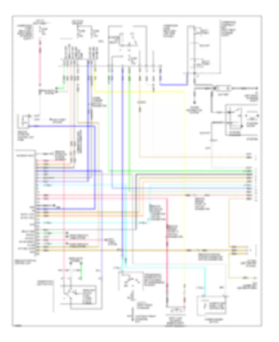
Remote Starting Wiring Diagram (1 of 2) for Honda Pilot EX 2014

Remote Starting Wiring Diagram (1 of 2) for Honda Pilot EX 2014 https://portal-diagnostov.com/license.html
https://portal-diagnostov.com/license.html Automotive Electricians Portal FZCO Automotive Electricians Portal FZCO
Get access to all wiring diagrams of the carDownload PDF file

List of elements for Remote Starting Wiring Diagram (1 of 2) for Honda Pilot EX 2014:

  • (top right front of engine) g101
  • 120a
  • 50a
  • Antenna input
  • Anti- theft system
  • Anti-theft system
  • B-canh
  • B-canl
  • Battery
  • C101
  • C102
  • C202
  • Combi gnd
  • Combination light switch
  • Combination light switch connector
  • Computer data lines system
  • Dlc (under left center of dash)
  • Eld unit
  • F29
  • Fr wip int
  • Fuse 10a
  • Fuse 20a
  • Fuse 7.5a
  • G1 (left front of engine compt)
  • G20
  • G40
  • Gnd
  • H/l 0ff sw
  • H/l off sw
  • Headlight switch 0) off 1) park 2) auto 3) head
  • Headlights system
  • Hot at all times
  • Hot in on or start
  • Ig1 fuel pump
  • Ig1 meter
  • Ig1 rly coil
  • Ig2 rly coil
  • Imo cd (snet)
  • Intermittent dwell time controller
  • J/c c111 (right front of engine)
  • J/c c422 (left center of dash)
  • K-line
  • Micu
  • Multi- fuse 1
  • Multi- fuse 2
  • Pnk
  • Power distribution system
  • Q15
  • R12
  • Red
  • Relay gnd
  • Remote engine pnk start (1) (option connector)
  • Remote engine start (2) (option connector)
  • Remote starting control unit
  • Remote starting control unit fuse
  • Remote starting system antenna
  • Remote starting system connector (option connector)
  • S11
  • S13
  • Scs
  • Shift lock solenoid (base of shift lever assembly)
  • Small lt sw
  • Starter
  • Starter cut relay 1
  • Starter motor
  • Starter solenoid
  • Sts
  • Transmission range switch (bottom rear of transmission housing)
  • Under-dash fuse/ relay box (left end of dash)
  • Under-hood fuse/ relay box (right rear of engine compt)
  • Under-hood fuse/relay box (right rear of engine compt)
  • Wiper/ washer switch connector
  • Wiper/washer switch

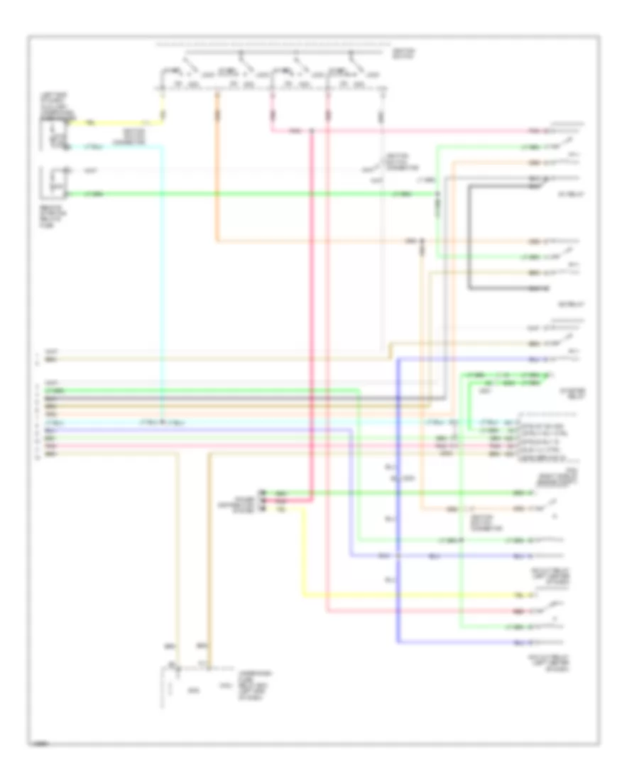
Remote Starting Wiring Diagram (2 of 2) for Honda Pilot EX 2014

Remote Starting Wiring Diagram (2 of 2) for Honda Pilot EX 2014 https://portal-diagnostov.com/license.html
https://portal-diagnostov.com/license.html Automotive Electricians Portal FZCO Automotive Electricians Portal FZCO
Get access to all wiring diagrams of the carDownload PDF file

List of elements for Remote Starting Wiring Diagram (2 of 2) for Honda Pilot EX 2014:

  • (left end of dash) auxiliary under-dash fuse holder
  • (scs) ser chk in
  • (sls) vlv ctrl
  • (strld) rly in
  • (strly) rly ctrl
  • (sts) st sw sig
  • 40a
  • A28
  • A31
  • A32
  • Acc
  • Acc cut relay (left center of dash)
  • C201
  • C203
  • C303
  • F11
  • Ig1 relay
  • Ig2 cut relay (left center of dash)
  • Ig2 relay
  • Ignition switch
  • Ignition switch connector
  • Lock
  • Micu
  • Pcm (right side of engine compt)
  • Pnk
  • Power distribution system
  • Red
  • Remote starting relays fuse
  • Scs
  • Start
  • Starter relay
  • Sts 7.5a
  • Under-dash fuse/ relay box (left end of dash)

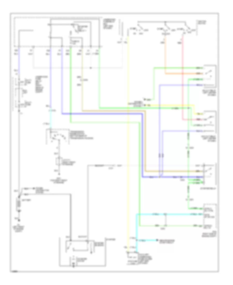
Starting Wiring Diagram for Honda Pilot EX 2014

Starting Wiring Diagram for Honda Pilot EX 2014 https://portal-diagnostov.com/license.html
https://portal-diagnostov.com/license.html Automotive Electricians Portal FZCO Automotive Electricians Portal FZCO
Get access to all wiring diagrams of the carDownload PDF file

List of elements for Starting Wiring Diagram for Honda Pilot EX 2014:

  • (strld) rly in
  • (strly) rly ctrl
  • (sts) st sw sig
  • 120a
  • 50a
  • A28
  • A31
  • Acc
  • Acc cut relay (left center of dash)
  • Auxiliary under-dash fuse holder (left end of dash)
  • Battery
  • C101
  • C102
  • C201
  • C202
  • C203
  • C303
  • Eld unit
  • F29
  • Fuse 23 7.5a
  • G1 (left front of engine compt)
  • G101 (top right front of engine)
  • G20
  • Ig2 cut relay (left center of dash)
  • Ignition switch
  • J/c c111 (right front of engine)
  • Lock
  • Multi- fuse
  • Pcm (right side of engine compt)
  • Power distribution system
  • Q15
  • Red
  • Remote engine start circuit
  • Start
  • Starter
  • Starter cut relay 1
  • Starter motor
  • Starter relay
  • Starter solenoid
  • Sts fuse 7.5a
  • Transmission range switch (bottom rear of transmission housing)
  • Under-dash fuse/relay box (left end of dash)
  • Under-hood fuse/ relay box (right rear of engine compt)