AUTOMOTIVE ELECTRICIANS PORTAL

STARTING/CHARGING – Land Rover Range Rover Supercharged 2013 – SYSTEM WIRING DIAGRAMS

STARTING/CHARGING

Charging Wiring Diagram for Land Rover Range Rover Supercharged 2013

Charging Wiring Diagram for Land Rover Range Rover Supercharged 2013 https://portal-diagnostov.com/license.html
https://portal-diagnostov.com/license.html Automotive Electricians Portal FZCO Automotive Electricians Portal FZCO
Download PDF file

List of elements for Charging Wiring Diagram for Land Rover Range Rover Supercharged 2013:

  • 500a
  • Battery
  • Battery junction box 2 (right side of cargo area)
  • Battery monitoring system module (connected to battery terminal)
  • C11-m1
  • C11-m2
  • C12-a1
  • C12-a2
  • C1dc12b
  • C1dc12g
  • C2mc01a
  • C4dc02b
  • C4dc03a
  • C4dc27
  • C4dc56b
  • C4df10a
  • C4df10c
  • Cable junction stud (lower right rear of c1dc12e engine compt)
  • Computer data lines system
  • Fusible link 1 450a
  • Fusible wire link
  • G4d150d (on right side of cargo area)
  • G4d178 (behind left rear passenger seat)
  • Gateway module (behind right side of dash)
  • Generator
  • Hs can h
  • Hs can l
  • Instrument cluster
  • Jump start terminal (right side of engine compt)
  • Lin
  • Lin 3
  • Mega fuse
  • Mon
  • Nca
  • Red
  • Starter mega fuse 500a
  • Starter motor
  • System module
  • Transit relay (left rear of cargo area)
  • W/ battery monitoring
  • W/ transit relay
  • W/o battery monitoring
  • W/o transit relay

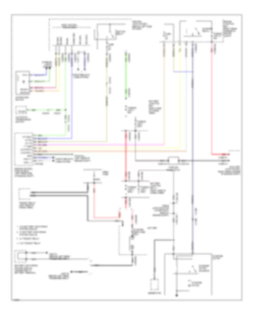
Starting Wiring Diagram for Land Rover Range Rover Supercharged 2013

Starting Wiring Diagram for Land Rover Range Rover Supercharged 2013 https://portal-diagnostov.com/license.html
https://portal-diagnostov.com/license.html Automotive Electricians Portal FZCO Automotive Electricians Portal FZCO
Get access to all wiring diagrams of the carDownload PDF file

List of elements for Starting Wiring Diagram for Land Rover Range Rover Supercharged 2013:

  • 500a
  • Automatic transmission switch
  • Auxiliary junction box (right rear corner of engine compt)
  • Battery
  • Battery junction box (right side of cargo area)
  • Battery junction box 2 (right side of cargo area)
  • Battery monitoring system module (connected to battery terminal)
  • Body control module (bcm)
  • C11-m1
  • C11-m2
  • C1bb01aa
  • C1bb01b
  • C1bf01a
  • C1bf01h
  • C1dc12b
  • C1dc12e
  • C1dc13a
  • C1e120b
  • C2bp01b
  • C2bp01d
  • C2bp01e
  • C2bp01f
  • C2bp01g
  • C31-a1
  • C31-a2
  • C31-a2 c31-a1
  • C32-m1
  • C32-m2
  • C3dc13a
  • C4bf01a
  • C4bf01d
  • C4bf01j
  • C4dc02b
  • C4dc03a
  • C4df10a
  • C4df10c
  • C4df10e
  • Cable junction stud (lower right rear of engine compt)
  • Can h 1
  • Can l 1
  • Central junction box (behind left side of dash)
  • Computer data lines system
  • Crank req
  • Engine control module (ecm) (left rear side of engine compt)
  • Engine junction box (right rear corner of engine compt)
  • Fuse 5a
  • Fusible link 1 250a
  • Fusible link 1 450a
  • Fusible link 15 40a
  • Fusible link 2 350a
  • Fusible link 4 60a
  • G1d121al (left rear of engine compt)
  • G4d178 (behind left rear passenger seat)
  • Generator
  • Gnd
  • Hs can h
  • Hs can l
  • I s t15
  • I s t50
  • I s tnsw
  • I t t50r
  • Ignition relay
  • Interior lights system
  • Mega fuse
  • Nca
  • O s strth
  • O s strtl
  • Pn sig
  • Red
  • Ss sw1
  • Ss sw2
  • Starter mega fuse 500a
  • Starter motor
  • Starter motor solenoid
  • Starter relay
  • Stop/start switch
  • System module
  • Through panel stud
  • Transit relay (left rear of cargo area)
  • W/ battery monitoring system module
  • W/ transit relay
  • W/o battery monitoring
  • W/o transit relay