AUTOMOTIVE ELECTRICIANS PORTAL

STARTING/CHARGING – Mitsubishi Lancer DE 2008 – SYSTEM WIRING DIAGRAMS

STARTING/CHARGING

Charging Wiring Diagram for Mitsubishi Lancer DE 2008

Charging Wiring Diagram for Mitsubishi Lancer DE 2008 https://portal-diagnostov.com/license.html
https://portal-diagnostov.com/license.html Automotive Electricians Portal FZCO Automotive Electricians Portal FZCO
Download PDF file

List of elements for Charging Wiring Diagram for Mitsubishi Lancer DE 2008:

  • (generator malfunction light)
  • 120a
  • 7.5a
  • B-108 b-09
  • B-109 b-10
  • Battery
  • C-317
  • Can
  • Circuit
  • Combination meter
  • Computer data lines system
  • Cpu
  • Engine compartment fuse/relay box (left side of engine compt)
  • Engine control module (except evolution: left rear of engine compt) (evolution: near relay box)
  • Etacs-ecu (behind left end of dash)
  • Evolution
  • Except evolution
  • Fuse
  • Fuse 5
  • Fusible link 33
  • Fusible link 36
  • Fusible link box (except evolution: next to battery) (evolution: near relay box)
  • G19 (except evolution) (left side engine compt)
  • G21 (evolution) (near battery)
  • G3 (except evolution) (under right front kick panel)
  • Generator
  • Generator malfunction light
  • Hot w/ ig1 relay energized
  • Lcd
  • Led drive circuit
  • Pnk
  • Starting circuit
  • Transceiver

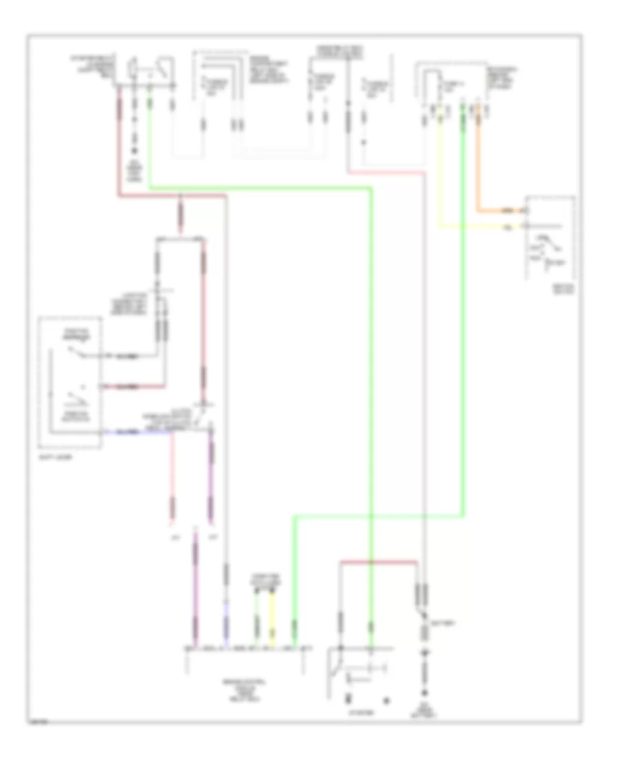
Starting Wiring Diagram, Evolution for Mitsubishi Lancer DE 2008

Starting Wiring Diagram, Evolution for Mitsubishi Lancer DE 2008 https://portal-diagnostov.com/license.html
https://portal-diagnostov.com/license.html Automotive Electricians Portal FZCO Automotive Electricians Portal FZCO
Získajte prístup ku všetkým schémam zapojenia automobiluDownload PDF file

List of elements for Starting Wiring Diagram, Evolution for Mitsubishi Lancer DE 2008:

  • (near relay box) fusible link box
  • 10a
  • 120a
  • 30a
  • 80a
  • A/t
  • Acc
  • B-09
  • B-10
  • Battery
  • C-304
  • C-309
  • C-315
  • C-317
  • Clutch interlock switch (top of clutch pedal assembly)
  • Computer data lines system
  • Engine compartment relay box (left side of engine compt)
  • Engine control module (near relay box)
  • Etacs-ecu (behind left end of dash)
  • Fuse 14
  • Fusible link 24
  • Fusible link 34
  • Fusible link 36
  • G12 (near high horn)
  • G21 (near battery)
  • Ignition switch
  • Junction connector 7 (behind left side of dash)
  • Lock
  • M/t
  • Position switch (n)
  • Position switch (p)
  • Run
  • Shift lever
  • Start
  • Starter
  • Starter relay (in engine compt relay box)

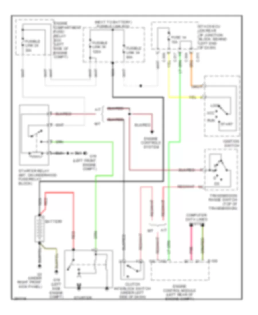
Starting Wiring Diagram, Except Evolution for Mitsubishi Lancer DE 2008

Starting Wiring Diagram, Except Evolution for Mitsubishi Lancer DE 2008 https://portal-diagnostov.com/license.html
https://portal-diagnostov.com/license.html Automotive Electricians Portal FZCO Automotive Electricians Portal FZCO
Získajte prístup ku všetkým schémam zapojenia automobiluDownload PDF file

List of elements for Starting Wiring Diagram, Except Evolution for Mitsubishi Lancer DE 2008:

  • (next to battery) fusible link box
  • 10a
  • 120a
  • 30a
  • 80a
  • A/t
  • Acc
  • B-109
  • Battery
  • C-304
  • C-309
  • C-315
  • C-317
  • Clutch interlock switch (under left side of dash)
  • Computer data lines system
  • Engine compartment fuse/ relay box (left side of engine compt)
  • Engine control module (left rear of engine compt)
  • Engine controls system
  • Etacs-ecu (on rear of junction block, behind left end of dash)
  • Fuse 14
  • Fusible link 24
  • Fusible link 34
  • Fusible link 36
  • G18 (left front engine compt)
  • G19 (left side engine compt)
  • G3 (under right front kick panel)
  • Ignition switch
  • Lock
  • M/t
  • Nca
  • Pnk
  • Red
  • Run
  • Start
  • Starter
  • Starter relay (m/t: on underhood fuse/relay block)
  • Transmission range switch (top of transmission)