
 Čeština
 Dansk
Dansk Deutsch
 Ελληνικά
 English
 English
 Español
 Suomi
Suomi Français
 Français
 עברית
עברית Hrvatski
 Magyar
 Italiano
 日本語
日本語 한국어
한국어 Nederlands
 Português
 Português
 Română
 Русский
 Slovenčina
 Slovenščina
 Svenska
 Türkçe
 中文 (中国)

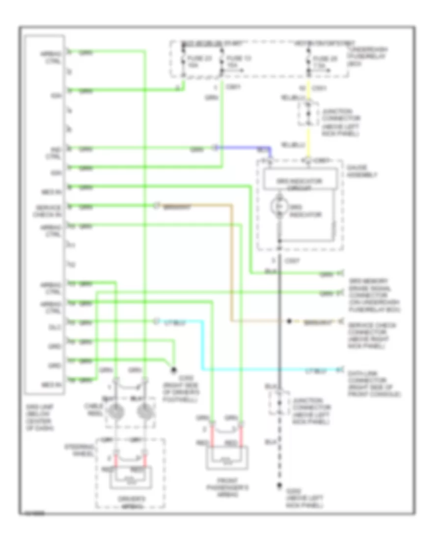
SUPPLEMENTAL RESTRAINTS
Supplemental Restraints Wiring Diagram for Acura Integra GS-R 1999
List of elements for Supplemental Restraints Wiring Diagram for Acura Integra GS-R 1999:

ANTI-THEFTAIR CONDITIONINGBODY CONTROL MODULESANTI-LOCK BRAKESCRUISE CONTROLCOMPUTER DATA LINESGROUND DISTRIBUTIONDEFOGGERSCOOLING FANENGINE PERFORMANCEEXTERIOR LIGHTSHEADLIGHTSINSTRUMENT CLUSTERHORNPOWER DISTRIBUTIONPOWER ANTENNAPOWER MIRRORSPOWER DOOR LOCKSINTERIOR LIGHTSSHIFT INTERLOCKRADIOPOWER TOP/SUNROOFPOWER WINDOWSTRANSMISSIONSTARTING/CHARGINGSUPPLEMENTAL RESTRAINTSWARNING SYSTEMSTRUNK, TAILGATE, FUEL DOORWIPER/WASHER