SUPPLEMENTAL RESTRAINTS
Supplemental Restraints Wiring Diagram for Chevrolet Astro 2004
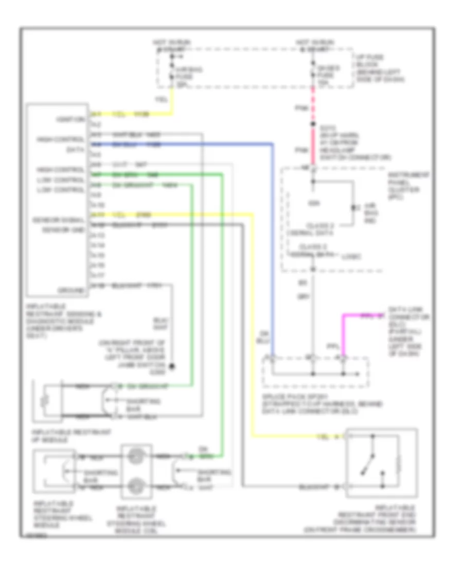
List of elements for Supplemental Restraints Wiring Diagram for Chevrolet Astro 2004:
- (on right front of "a" pillar, above left front door jamb switch) g300
- A10
- A11
- A12
- A13
- A14
- A15
- A16
- A17
- A18
- Air bag fuse 10a
- Air bag ind.
- Class 2 serial data
- Data
- Data link connector (dlc) (partial) (under left side of dash)
- Gages fuse 10a
- Ground
- High control
- Hot in run & start
- I/p fuse block (behind left side of dash)
- Ign
- Ignition
- Inflatable restraint front end discriminating sensor (on front frame crossmember)
- Inflatable restraint i/p module
- Inflatable restraint sensing & diagnostic module (under driver's seat)
- Inflatable restraint steering wheel module
- Inflatable restraint steering wheel module coil
- Instrument panel cluster (ipc)
- Logic
- Low control
- Nca
- Pnk
- S213 (in i/p harn, 41 cm from headlamp switch connector)
- Sensor gnd
- Sensor signal
- Shorting bar
- Splice pack sp261 (strapped to i/p harness, behind data link connector (dlc)
 Čeština
 Dansk
Dansk Deutsch
 Ελληνικά
 English
 Español
 Suomi
Suomi Français
 Français
 עברית
עברית Hrvatski
 Magyar
 Italiano
 日本語
日本語 한국어
한국어 Nederlands
 Polski
 Português
 Português
 Română
 Русский
 Slovenčina
 Slovenščina
 Svenska
 Türkçe
 中文 (中国)
 English