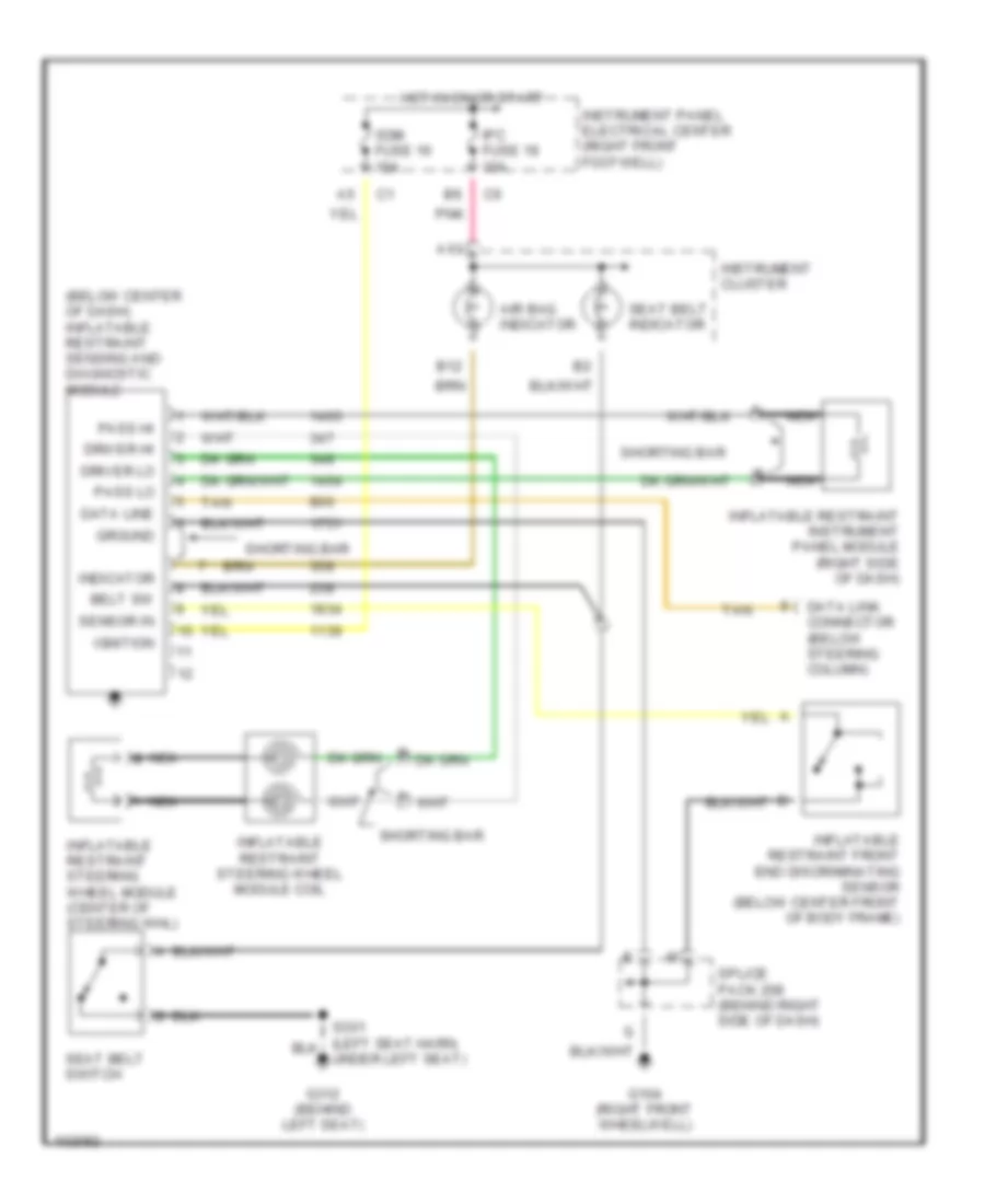
SUPPLEMENTAL RESTRAINTS
Supplemental Restraint Wiring Diagram for Chevrolet Corvette 1998
List of elements for Supplemental Restraint Wiring Diagram for Chevrolet Corvette 1998:
- (below center of dash) inflatable restraint sensing and diagnostic module
- A13
- Air bag indicator
- B12
- Belt sw
- Data line
- Data link connector (below steering column)
- Driver hi
- Driver lo
- G104 (right front wheelwell)
- G312 (behind left seat)
- Ground
- Hot in on or start
- Ignition
- Indicator
- Inflatable restraint front end discriminating sensor (below center front of body frame)
- Inflatable restraint instrument panel module (right side of dash)
- Inflatable restraint steering wheel module (center of steering whl)
- Inflatable restraint steering wheel module coil
- Instrument cluster
- Instrument panel electrical center (right front footwell)
- Ipc fuse 19 10a
- Nca
- Nca b
- Pass hi
- Pass lo
- Pnk
- S301 (left seat harn, under left seat)
- Sdm fuse 16 15a
- Seat belt indicator
- Seat belt switch
- Sensor in
- Shorting bar
- Splice pack 208 (behind right side of dash)
- Tan
 Čeština
 Dansk
Dansk Deutsch
 Ελληνικά
 English
 Español
 Suomi
Suomi Français
 Français
 עברית
עברית Hrvatski
 Magyar
 Italiano
 日本語
日本語 한국어
한국어 Nederlands
 Polski
 Português
 Português
 Română
 Русский
 Slovenčina
 Slovenščina
 Svenska
 Türkçe
 中文 (中国)
 English