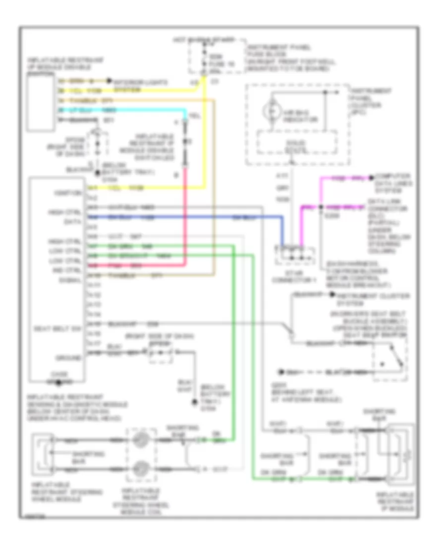
SUPPLEMENTAL RESTRAINTS
Supplemental Restraints Wiring Diagram for Chevrolet Corvette 2004
List of elements for Supplemental Restraints Wiring Diagram for Chevrolet Corvette 2004:
- (below
- (below battery tray) g104
- (dash harness, 5 cm from blower motor control module breakout)
- (in driver's seat belt buckle assembly) (open when buckled) seat belt switch
- (right side of dash) sp208
- A10
- A11
- A12
- A13
- A14
- A15
- A16
- A17
- A18
- Air bag indicator
- B nca
- Bar
- Case ground
- Computer data lines system
- Data
- Data link connector (dlc) (partial) (under dash, below steering column)
- G205 (behind left seat, at antenna module)
- Ground
- High ctrl
- Hot in on & start
- Ignition
- Ind ctrl
- Inflatable restraint i/p module disable switch
- Inflatable restraint ip module
- Inflatable restraint ip module disable switch led
- Inflatable restraint sensing & diagnostic module (below center of dash, under hvac control head)
- Inflatable restraint steering wheel module
- Inflatable restraint steering wheel module coil
- Instrument cluster system
- Instrument panel cluster (ipc)
- Instrument panel fuse block (in right front footwell, mounted to toe board)
- Interior lights system
- Low ctrl
- Nca
- Pnk
- S206
- Sdm fuse 16 15a
- Seat belt sw
- Shorting
- Shorting bar
- Signal
- Solid state
- Sp208 (right side of dash)
- Star connector 1
 Čeština
 Dansk
Dansk Deutsch
 Ελληνικά
 English
 Español
 Suomi
Suomi Français
 Français
 עברית
עברית Hrvatski
 Magyar
 Italiano
 日本語
日本語 한국어
한국어 Nederlands
 Polski
 Português
 Português
 Română
 Русский
 Slovenčina
 Slovenščina
 Svenska
 Türkçe
 中文 (中国)
 English