SUPPLEMENTAL RESTRAINTS
Supplemental Restraint Wiring Diagram for Chrysler PT Cruiser Touring 2002
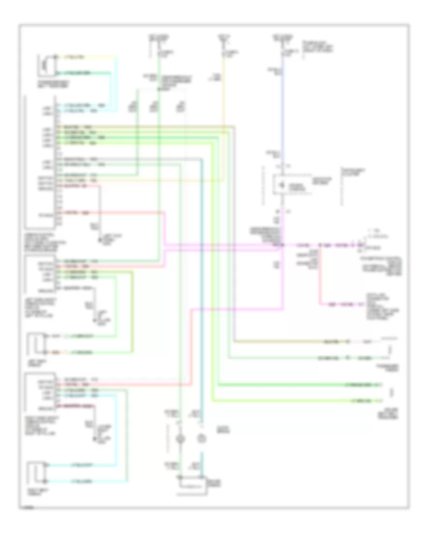
List of elements for Supplemental Restraint Wiring Diagram for Chrysler PT Cruiser Touring 2002:
- (at base of left "b" pillar)
- (left "b" pillar) g303
- (left kick panel) g202
- (lower right "b" pillar) g304
- (near breakout for brake shift interlock solenoid) s201
- 1.6l
- 2.ol/2.4l
- Air bag warning
- Airbag control module (orc) (on tunnel floor pan, between shifter & parking brake)
- Clock- spring
- D25
- Data link connector (dlc) (partial) (under left side of dash, near kick panel)
- Driver airbag
- Driver seat belt tensioner
- F15
- F25
- Fuse 10 10a
- Fuse 5 10a
- Fuse 9 10a
- Fuse block (at lower left front of dash)
- Ground
- Hot in run
- Hot in run or start
- Ignition
- Indicator drivers
- Instrument cluster
- Left seat airbag
- Left side impact airbag control module
- Line 1
- Line 2
- Passenger airbag
- Passenger seat belt tensioner
- Pci bus
- Powertrain control module (on firewall, behind power distribution center)
- R31
- R32
- R33
- R34
- R42
- R43
- R44
- R45
- R53
- R54
- R55
- R56
- Right seat airbag
- Right side impact airbag control module (at base of right "b" pillar)
- S126 (near data link connector (dlc))
- Z134
- Z135
 Čeština
 Dansk
Dansk Deutsch
 Ελληνικά
 English
 Español
 Suomi
Suomi Français
 Français
 עברית
עברית Hrvatski
 Magyar
 Italiano
 日本語
日本語 한국어
한국어 Nederlands
 Polski
 Português
 Português
 Română
 Русский
 Slovenčina
 Slovenščina
 Svenska
 Türkçe
 中文 (中国)
 English