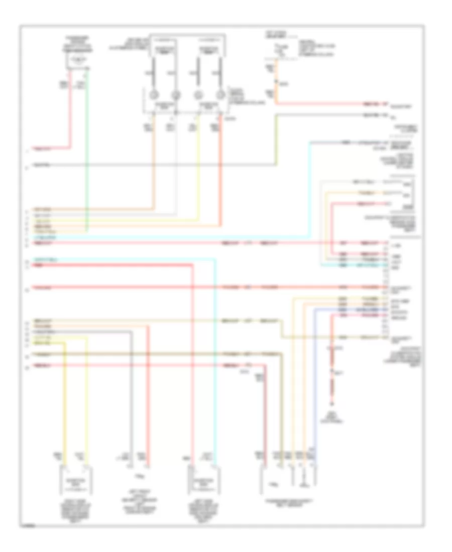
SUPPLEMENTAL RESTRAINTS
Supplemental Restraints Wiring Diagram (1 of 2) for Ford Crown Victoria 2011
 https://portal-diagnostov.com/license.html
Automotive Electricians Portal FZCO
Automotive Electricians Portal FZCO
https://portal-diagnostov.com/license.html
https://portal-diagnostov.com/license.html
Automotive Electricians Portal FZCO
Automotive Electricians Portal FZCO
List of elements for Supplemental Restraints Wiring Diagram (1 of 2) for Ford Crown Victoria 2011:
- (body main harness, near breakout to restraints control module)
- (main body wiring harness, near breakout to c919)
- (main wiring harness, in breakout to instrument cluster) s239
- (right kick panel)
- C175b
- C237
- C248
- C260
- C310a
- C310b
- C311
- C312
- C315
- C316
- Central junction box (cjb) (left of steering column)
- Chime req
- Computer data lines system
- Driver safety belt retractor pretensioner (base of left ``b" pillar)
- Driver side safety belt sensor
- Driver side seat position sensor (below driver seat)
- Feed
- Fuse 10a
- G201
- G201 (right kick panel)
- Hot in run or start
- Iso
- Left side impact sensor (w/ side air bag) (base of left "b" pillar)
- Logic gnd
- Nca
- Ocs can hi
- Ocs can low
- Pad ind
- Passenger air bag module (right side of dash)
- Passenger safety belt retractor pretensioner (base of right ``b" pillar)
- Pin shorting bars engaged when module connector is disconnected from harness shorting bars are connected between pins: 1-2, 21-22 conn. c310b
- Powertrain control module (pcm) (left rear of engine compt)
- Rdi
- Red
- Restraints control module (below center of dash)
- Return
- Right front impact severity sensor (right front of engine compartment)
- Right side impact sensor (w/ side air bag) (base of right "b" pillar)
- Ril
- Run start
- S213 (main body wiring harness, near breakout to g200)
- S217
- S301 (power seats harness, in breakout to c311)
- S305
- Shorting bar
- Stage 1
- Stage 2
- Vid 1
- Vid 2
Supplemental Restraints Wiring Diagram (2 of 2) for Ford Crown Victoria 2011
List of elements for Supplemental Restraints Wiring Diagram (2 of 2) for Ford Crown Victoria 2011:
- Bts
- Bts rtn
- Bts vref
- C2145a
- C218a
- C312
- Central junction box (cjb) (left of steering column)
- Clock- spring (top of steering column)
- Driver air bag module (in steering wheel)
- Fuse 10a
- G201 (right kick panel)
- Gnd
- Ground
- Hot in run or start
- Hs safety can
- Hs safety can -
- Instrument cluster
- Left front impact severity sensor (left front of engine compartment)
- Left side air bag module (resistor w/o side air bags) (driver's seat)
- Lighting control module (under center of dash)
- Nca
- Occupant classification sensor (ocs) (passenger seat)
- Occupant classification system module (under passenger seat)
- Passenger air bag deactivation (pad) indicator
- Passenger side safety belt sensor
- Pwr
- Rcm/chime request
- Red
- Right side air bag module (resistor w/o side air bags) (passenger's seat)
- Ril
- Run/start
- S217
- S276
- Shorting bar
- Sig
- Tan/ red
- Tan/red
- V ign
- Vout
- Vref

 Čeština
 Dansk
Dansk Deutsch
 Ελληνικά
 English
 Español
 Suomi
Suomi Français
 Français
 עברית
עברית Hrvatski
 Magyar
 Italiano
 日本語
日本語 한국어
한국어 Nederlands
 Polski
 Português
 Português
 Română
 Русский
 Slovenčina
 Slovenščina
 Svenska
 Türkçe
 中文 (中国)