SUPPLEMENTAL RESTRAINTS
Supplemental Restraints Wiring Diagram for Ford Econoline E250 2001
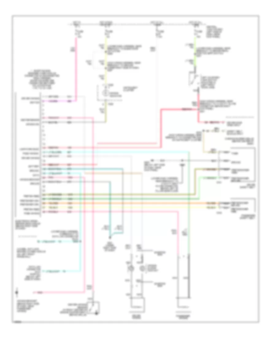
List of elements for Supplemental Restraints Wiring Diagram for Ford Econoline E250 2001:
- (lower dash harness, in breakout to data link connector (dlc)) s228
- (lower dash harness, near breakout to 8 cavity gray in-line connector, behind left "b" pillar near floor)
- (lower dash harness, near breakout to blend door actuator) s265
- (lower dash harness, near breakout to brake pedal position (bpp) switch) s221
- (main wiring harness, near breakout to 14 cavity in-line connector, behind right kick panel) s201
- (main wiring harness, near breakout to ground under right side of dash) s267
- 4-wheel anti-lock brakes (4wabs) module (on left front frame rail)
- Air bag bracket
- Air bag bracket (behind right side of dash, near passenger air bag)
- Air bag ind
- Air bag indicator
- Air bag sliding contact
- Battery
- C226
- C341
- C342
- Center air bag sensor (in front center of engine compartment, behind grille)
- Center sensor
- Central junction box (left side of dash, near kick panel)
- Data
- Data link connector (dlc) (partial) (below left side of dash)
- Driver air bag
- Driver door open input
- Driver safety belt
- Electronic crash sensor (ecs) module (behind right side of dash)
- Fuse 10a
- Fuse 15a
- Fuse 5a
- G201 (under right side of dash)
- G202 (below left side of dash, near kick panel)
- Ground
- Hot at all times
- Hot in run
- Hot in run or start
- Ignition
- Instrument cluster
- Lamp/warn buzz
- Left courtesy lamp switch (mounted in left front door jamb)
- Nca
- Pass air bag
- Passenger air bag
- Passenger safety belt
- Pnk
- Preten feed
- Preten return
- Pretensioner feed
- Pretensioner nca
- Pretensioner return
- Red/ pnk
- Red/pnk
- Return
- S235
- S275 (main wiring harness, near breakout to connector c225 on instrument cluster)
- Safety belt buckle input
- Shorting bar
- Shorting bar engaged when module connector is disconnected from harness (shorting bars are connected between following pins: 1-15, 7-21 & 14-28)
- Timer
- Warning buzzer module (behind center of dash)
 Čeština
 Dansk
Dansk Deutsch
 Ελληνικά
 English
 Español
 Suomi
Suomi Français
 Français
 עברית
עברית Hrvatski
 Magyar
 Italiano
 日本語
日本語 한국어
한국어 Nederlands
 Polski
 Português
 Português
 Română
 Русский
 Slovenčina
 Slovenščina
 Svenska
 Türkçe
 中文 (中国)
 English