SUPPLEMENTAL RESTRAINTS
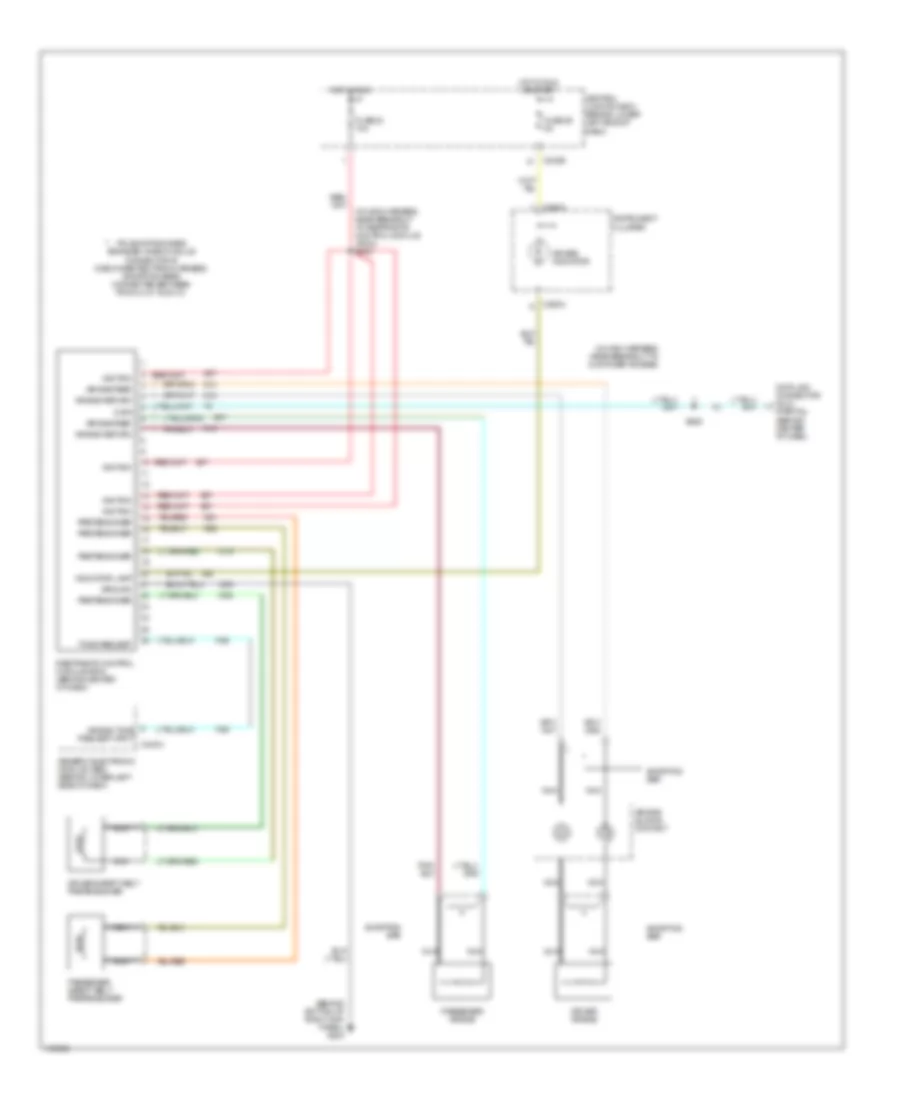
Supplemental Restraints Wiring Diagram, Early Production for Ford Excursion 2001
 https://portal-diagnostov.com/license.html
Automotive Electricians Portal FZCO
Automotive Electricians Portal FZCO
https://portal-diagnostov.com/license.html
https://portal-diagnostov.com/license.html
Automotive Electricians Portal FZCO
Automotive Electricians Portal FZCO
List of elements for Supplemental Restraints Wiring Diagram, Early Production for Ford Excursion 2001:
- (behind bottom of right kick panel) g203
- (in main harness, near breakout to air bag diagnostic module) s202
- (in main harness, near breakout to customer access)
- (partial) (behind center of dash)
- Air bag diagnostic module (in center of dash)
- Air bag indicator
- Air bag sliding contact
- Air bag tone request input
- C240a
- C242b
- C250a
- Central junction box (behind lower left side of dash)
- Data
- Data link connector (dlc)
- Driver air bag
- Fuse 23 10a
- Fuse 29 5a
- Generic electronic module (gem) (behind lower left side of dash)
- Ground
- Hot in run
- Hot in run or start
- Ignition
- Indicator
- Instrument cluster
- Monitor
- Nca
- Output
- Passenger air bag
- Pin shorting bars engaged when module connector is disconnected from harness: (shorting bars connected between following pins: 1-15, 2-13 & 14-28)
- Return
- S225
- Shorting bar
Supplemental Restraints Wiring Diagram, Late Production for Ford Excursion 2001
List of elements for Supplemental Restraints Wiring Diagram, Late Production for Ford Excursion 2001:
- (behind bottom of right kick panel) g203
- (in main harness, near breakout to customer access)
- (in main harness, near breakout to restraints control module (rcm)) s243
- Air bag feed
- Air bag indicator
- Air bag return
- Air bag sliding contact
- Air bag tone request input
- C240a
- C242b
- C250a
- Central junction box (behind lower left side of dash)
- Data
- Data link connector (dlc) (partial) (behind center of dash)
- Driver air bag
- Driver safety belt pretensioner
- Fuse 23 10a
- Fuse 29 5a
- Generic electronic module (gem) (behind lower left side of dash)
- Ground
- Hot in run
- Hot in run or start
- Ignition
- Indicator lamp
- Instrument cluster
- Nca
- Passenger air bag
- Passenger safety belt pretensioner
- Pin shorting bars engaged when module connector is disconnected from harness: (shorting bars connected between pins 3-4, 6-7 & 20-21)
- Pretensioner
- Restraints control module (rcm) (behind center of dash)
- S225
- Shorting bar
- Tone request

 Čeština
 Dansk
Dansk Deutsch
 Ελληνικά
 English
 Español
 Suomi
Suomi Français
 Français
 עברית
עברית Hrvatski
 Magyar
 Italiano
 日本語
日本語 한국어
한국어 Nederlands
 Polski
 Português
 Português
 Română
 Русский
 Slovenčina
 Slovenščina
 Svenska
 Türkçe
 中文 (中国)