SUPPLEMENTAL RESTRAINTS
Supplemental Restraints Wiring Diagram for Ford F550 Super Duty 2007
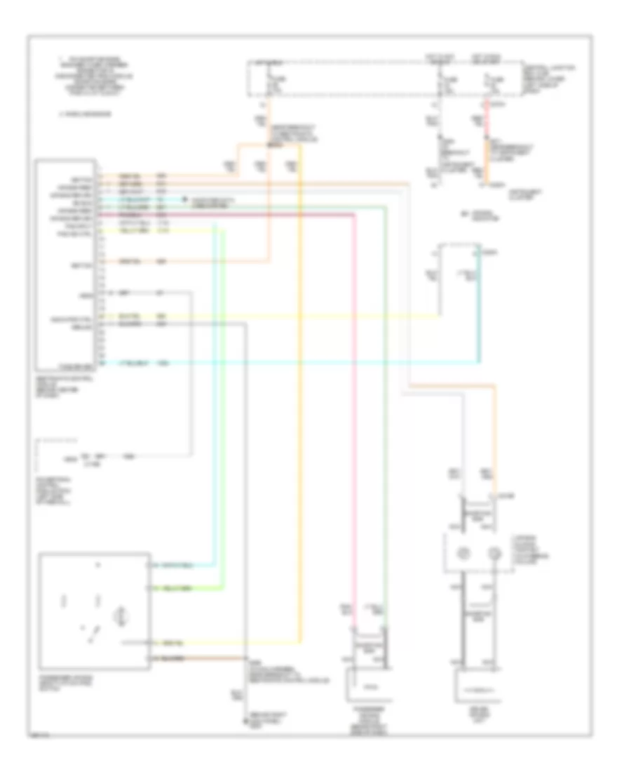
List of elements for Supplemental Restraints Wiring Diagram for Ford F550 Super Duty 2007:
- (behind right kick panel) g203
- (in steering column)
- Air bag feed
- Air bag indicator
- Air bag return
- Air bag sliding contact
- C175b
- C218b
- C220a
- C270a
- Central junction box (cjb) (behind lower left side of dash)
- Computer data lines system
- Driver air bag unit
- Fuse 10a
- Fuse 15a
- Gasoline engine
- Ground
- Hot in acc or run
- Hot in run
- Hot in run or start
- Ignition
- Indicator ctrl
- Instrument cluster
- Iso bus
- Nca
- Pad ind ctrl
- Pad input
- Passenger air bag deactivation (pad) switch
- Passenger air bag module (behind right side of dash)
- Pin shorting bars engaged when harness connector is disconnected from module: (shorting bars connected between pins 3-4, 6-7 & 20-21)
- Powertrain control module (pcm) (left side of firewall)
- Restraints control module (behind center of dash)
- S271 (near breakout to instrument cluster)
- S299 (in main harness, near breakout to restraints control module)
- Shorting bar
- Tone driver
- Vems
 Čeština
 Dansk
Dansk Deutsch
 Ελληνικά
 English
 Español
 Suomi
Suomi Français
 Français
 עברית
עברית Hrvatski
 Magyar
 Italiano
 日本語
日本語 한국어
한국어 Nederlands
 Polski
 Português
 Português
 Română
 Русский
 Slovenčina
 Slovenščina
 Svenska
 Türkçe
 中文 (中国)
 English