SUPPLEMENTAL RESTRAINTS
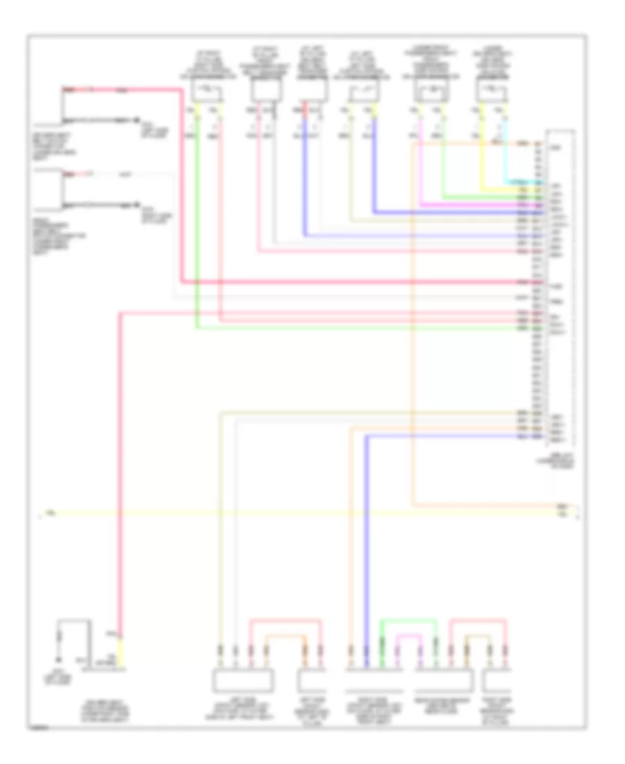
Supplemental Restraints Wiring Diagram, 2 Door (1 of 3) for Honda Accord EX 2010
 https://portal-diagnostov.com/license.html
Automotive Electricians Portal FZCO
Automotive Electricians Portal FZCO
https://portal-diagnostov.com/license.html
https://portal-diagnostov.com/license.html
Automotive Electricians Portal FZCO
Automotive Electricians Portal FZCO
List of elements for Supplemental Restraints Wiring Diagram, 2 Door (1 of 3) for Honda Accord EX 2010:
- (under left
- 5v stabilizer circuit/controller area network controller
- A10
- A11
- A12
- A13
- A14
- A15
- A16
- A17
- A18
- A19
- A20
- A21
- A22
- A23
- A24
- A25
- A26
- A27
- A28
- A29
- A30
- A31
- A32
- A33
- A34
- A35
- A36
- A37
- A38
- A39
- Cable reel (in steering column)
- Can hi
- Can lo
- Center junction box
- Compulsory turning- on circuit
- Computer data lines system
- Dlc
- Driver's air bag first inflator
- Driver's air bag second inflator
- Driver's junction box 1 (behind left kick panel)
- Driver's under-dash fuse/relay box (behind left kick panel)
- Fail-safe circuit
- Fast control area network transceiver
- Front passenger's air bag cut-off indicator
- Front passenger's air bag first inflator connector (behind left side of glove box)
- Front passenger's air bag second inflator connector (behind left side of glove box)
- Fuse 10a
- Fuse 7.5a
- G504 (under center console)
- Gauge control module
- Gnd
- Hazard warning switch
- Hot in on or start
- Ignition
- Interior lights system
- K-line
- La1+
- La1-
- La2+
- La2-
- Left front impact sensor (behind left side of bumper)
- Lfs+
- Lfs-
- P20
- Ptt
- Ra1+
- Ra1-
- Ra2+
- Ra2-
- Red
- Rfs+
- Rfs-
- Right front impact sensor (behind right side of front bumper)
- Seat belt reminder indicator
- Side air bag cut-off indicator
- Side of dash)
- Srs indicator
- Srs unit (under middle of dash)
- Steering wheel
- Warning drive circuit
- Wen
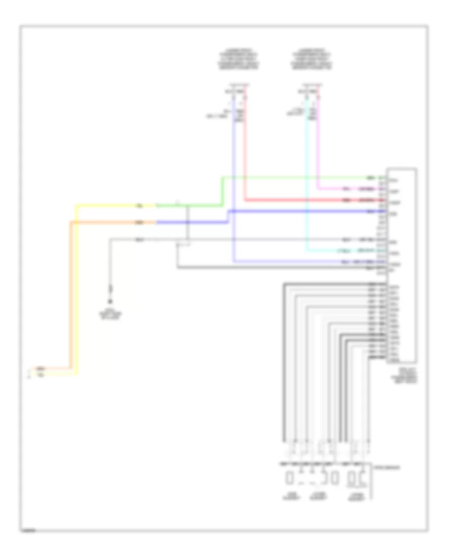
Supplemental Restraints Wiring Diagram, 2 Door (2 of 3) for Honda Accord EX 2010
List of elements for Supplemental Restraints Wiring Diagram, 2 Door (2 of 3) for Honda Accord EX 2010:
- (at left "b" pillar)
- (at left "c" pillar) left side curtain air bag inflator connector
- (at right "b" pillar)
- (at right "b" pillar) front passenger's seat belt tensioner connector
- (at right "c" pillar) right side curtain air bag inflator connector
- (center of rear floor)
- (on floor, at outer side of left front seat)
- (right side of floor)
- (under driver's seat)
- (under front passenger's seat) front passenger's side air bag inflator connector
- B10
- B11
- B12
- B13
- B14
- B15
- B16
- B17
- B18
- B19
- B20
- B21
- B22
- B23
- B24
- B25
- B26
- B27
- B28
- B29
- B30
- B31
- B32
- B33
- B34
- B35
- B36
- B37
- B38
- B39
- Driver's seat belt switch connector (under driver's seat)
- Driver's seat belt tensioner connector
- Driver's seat position sensor (under right side of driver's seat)
- Driver's side air bag inflator connector
- Flbc
- Frbc
- Front passenger's seat belt switch connector (under front passenger's seat)
- G701 (left side of floor)
- G702
- Impact sensor (1st) (on floor, at outer side of right front seat)
- Laca1+
- Laca1-
- Lbs1+
- Lbs1-
- Left side impact sensor (1st)
- Left side impact sensor (2nd) (at left "b" pillar)
- Lrp+
- Lrp-
- Lsa+
- Lsa-
- Ods
- Pnk
- Rbs1+
- Rbs1-
- Rca1+
- Rca1-
- Rear safing sensor
- Red
- Right side
- Right side impact sensor (2nd)
- Rrp+
- Rrp-
- Rsa+
- Rsa-
- Srs unit (under middle of dash)
- Ss+
Supplemental Restraints Wiring Diagram, 2 Door (3 of 3) for Honda Accord EX 2010
List of elements for Supplemental Restraints Wiring Diagram, 2 Door (3 of 3) for Honda Accord EX 2010:
- (in front passenger's seat back)
- (or
- (or red)
- (under front passenger's seat) inner side front passenger's weight sensor connector
- (under front passenger's seat) outer side front passenger's weight sensor connector
- D10
- D11
- D12
- D13
- D14
- D15
- D16
- D17
- D18
- G702 (right side of floor)
- Gnd
- Lower element
- Nca
- Ods
- Ods unit
- Opds sensor
- Os1l
- Os1s
- Os2l
- Os2s
- Os3l
- Os3s
- Os4l
- Os4s
- Os5l
- Os5s
- Os6l
- Os6s
- Os7l
- Os7s
- Pow
- Red
- Red)
- Side element
- Upper element
- Wsig
- Wsip
- Wsog
- Wsop
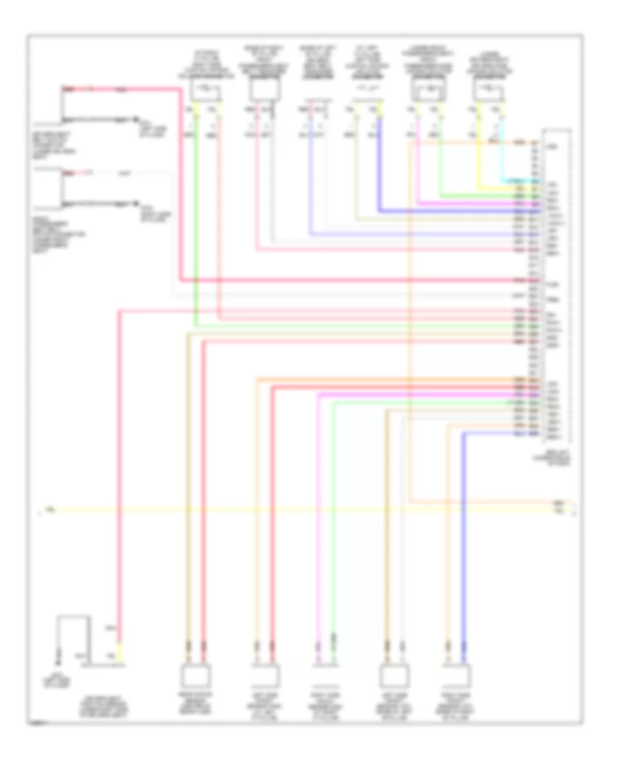
Supplemental Restraints Wiring Diagram, 4 Door (1 of 3) for Honda Accord EX 2010
List of elements for Supplemental Restraints Wiring Diagram, 4 Door (1 of 3) for Honda Accord EX 2010:
- (under left
- 5v stabilizer circuit/controller area network controller
- A10
- A11
- A12
- A13
- A14
- A15
- A16
- A17
- A18
- A19
- A20
- A21
- A22
- A23
- A24
- A25
- A26
- A27
- A28
- A29
- A30
- A31
- A32
- A33
- A34
- A35
- A36
- A37
- A38
- A39
- Cable reel (in steering column)
- Can hi
- Can lo
- Center junction box
- Compulsory turning- on circuit
- Computer data lines system
- Dlc
- Driver's air bag first inflator
- Driver's air bag second inflator
- Driver's junction box 1 (behind left kick panel)
- Driver's under-dash fuse/relay box (behind left kick panel)
- Fail-safe circuit
- Fast control area network transceiver
- Front passenger's air bag cut-off indicator
- Front passenger's air bag first inflator connector (behind left side of glove box)
- Front passenger's air bag second inflator connector (behind left side of glove box)
- Fuse 10a
- Fuse 7.5a
- G504 (under center console)
- Gauge control module
- Gnd
- Hazard warning switch
- Hot in on or start
- Ignition
- Interior lights system
- K-line
- La1+
- La1-
- La2+
- La2-
- Left front impact sensor (behind left side of bumper)
- Lfs+
- Lfs-
- P20
- Ptt
- Ra1+
- Ra1-
- Ra2+
- Ra2-
- Red
- Rfs+
- Rfs-
- Right front impact sensor (behind right side of front bumper)
- Seat belt reminder indicator
- Side air bag cut-off indicator
- Side of dash)
- Srs indicator
- Srs unit (under middle of dash)
- Steering wheel
- Warning drive circuit
- Wen
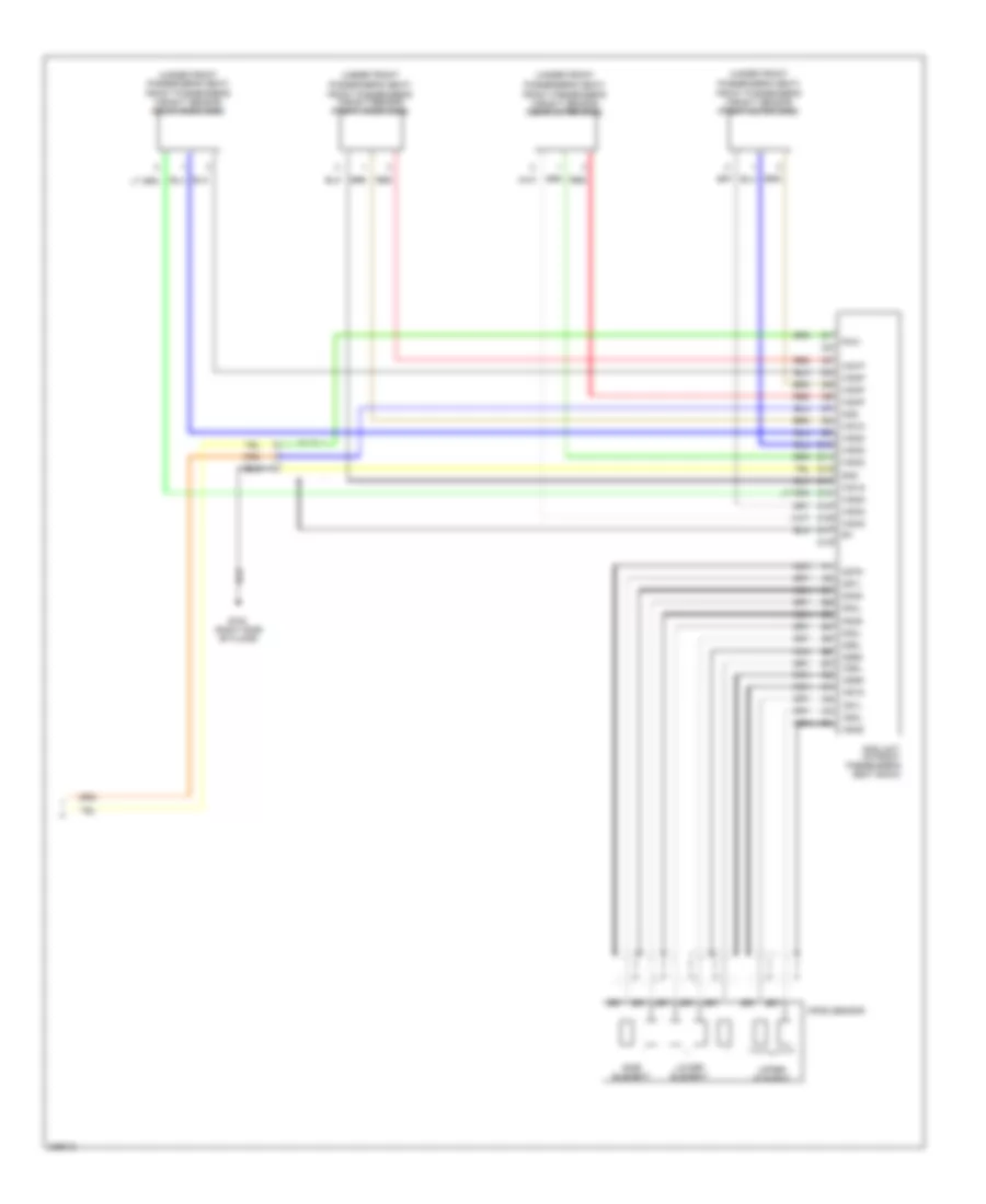
Supplemental Restraints Wiring Diagram, 4 Door (2 of 3) for Honda Accord EX 2010
List of elements for Supplemental Restraints Wiring Diagram, 4 Door (2 of 3) for Honda Accord EX 2010:
- (at left "c" pillar) left side curtain air bag inflator connector
- (at right "c" pillar) right side curtain air bag inflator connector
- (base of left "b" pillar)
- (base of right "b" pillar) front passenger's seat belt tensioner connector
- (right side of floor)
- (under driver's seat)
- (under front passenger's seat) front passenger's side air bag inflator connector
- (under middle of dash)
- B10
- B11
- B12
- B13
- B14
- B15
- B16
- B17
- B18
- B19
- B20
- B21
- B22
- B23
- B24
- B25
- B26
- B27
- B28
- B29
- B30
- B31
- B32
- B33
- B34
- B35
- B36
- B37
- B38
- B39
- Driver's seat belt switch connector (under driver's seat)
- Driver's seat belt tensioner connector
- Driver's seat position sensor (under right side of driver's seat)
- Driver's side air bag inflator connector
- Flbc
- Frbc
- Front passenger's seat belt switch connector (under front passenger's seat)
- G701 (left side of floor)
- G702
- Laca1+
- Laca1-
- Lbs1+
- Lbs1-
- Left side impact sensor (1st) (base of left "b" pillar)
- Left side impact sensor (2nd) (at left "c" pillar)
- Lrp+
- Lrp-
- Lsa+
- Lsa-
- Lsi2+
- Lsi2-
- Ods
- Pnk
- Rbs1+
- Rbs1-
- Rca1+
- Rca1-
- Rear safing sensor (center of rear floor)
- Red
- Right side impact sensor (1st) (base of right "b" pillar)
- Right side impact sensor (2nd) (at right "c" pillar)
- Rrp+
- Rrp-
- Rsa+
- Rsa-
- Rsi2+
- Rsi2-
- Srs unit
- Ss+
- Sss+
- Sss-
Supplemental Restraints Wiring Diagram, 4 Door (3 of 3) for Honda Accord EX 2010
List of elements for Supplemental Restraints Wiring Diagram, 4 Door (3 of 3) for Honda Accord EX 2010:
- (in front passenger's seat back)
- (under front passenger's seat)
- D10
- D11
- D12
- D13
- D14
- D15
- D16
- D17
- D18
- Front passenger's weight sensor (front inner side)
- Front passenger's weight sensor (front outer side)
- Front passenger's weight sensor (rear inner side)
- Front passenger's weight sensor (rear outer side)
- G702 (right side of floor)
- Gnd
- Lower element
- Nca
- Ods
- Ods unit
- Opds sensor
- Os1l
- Os1s
- Os2l
- Os2s
- Os3l
- Os3s
- Os4l
- Os4s
- Os5l
- Os5s
- Os6l
- Os6s
- Os7l
- Os7s
- Pow
- Red
- Side element
- Upper element
- Ws1d
- Ws1g
- Ws1p
- Ws2d
- Ws2g
- Ws2p
- Ws3d
- Ws3g
- Ws3p
- Ws4d
- Ws4g
- Ws4p

 Čeština
 Dansk
Dansk Deutsch
 Ελληνικά
 English
 Español
 Suomi
Suomi Français
 Français
 עברית
עברית Hrvatski
 Magyar
 Italiano
 日本語
日本語 한국어
한국어 Nederlands
 Polski
 Português
 Português
 Română
 Русский
 Slovenčina
 Slovenščina
 Svenska
 Türkçe
 中文 (中国)