SUPPLEMENTAL RESTRAINTS
Supplemental Restraints Wiring Diagram for Honda Insight 2005
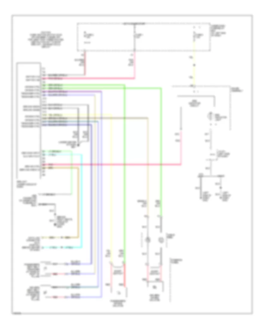
List of elements for Supplemental Restraints Wiring Diagram for Honda Insight 2005:
- (behind front seats, middle of floor) g502
- (left side of dash) g402
- (under center of dash) g501
- A10
- A11
- A12
- A13
- A14
- A15
- A16
- A17
- A18
- Air bag ctrl
- B17
- B18
- Cable reel
- Caution when ignition switch is on or has been turned off for less than three minutes use caution not to bump srs unit. air bags could deploy
- Connector (dlc) (partial) (behind center
- Data link
- Dlc input/out
- Driver's air bag inflator
- Driver's seat belt tensioner (at base of left "b" pillar)
- Fuse 1 10a
- Fuse 2 15a
- Fuse 6 7.5a
- Gauge assembly
- Ground (gnda)
- Ground (gndb)
- Hot in on or start
- Ignition (va)
- Ignition (vb)
- J/c 571 (left side of dash)
- Mes conn input
- Mes connector (in under dash fuse/relay box)
- Of dash)
- Passenger's air bag inflator
- Passenger's seat belt tensioner (at base of right "b" pillar)
- Pnk
- Red
- Service check in
- Short contact
- Srs ind ctrl
- Srs indicator circuit
- Srs indicator light
- Srs unit (under middle of dash)
- Steering wheel
- Tensioner ctrl
- Under dash fuse/relay box (at left end of dash)
- W/cvt
- W/o cvt
 Čeština
 Dansk
Dansk Deutsch
 Ελληνικά
 English
 English
 Español
 Suomi
Suomi Français
 Français
 עברית
עברית Hrvatski
 Magyar
 Italiano
 日本語
日本語 한국어
한국어 Nederlands
 Polski
 Português
 Português
 Română
 Slovenčina
 Slovenščina
 Svenska
 Türkçe
 中文 (中国)
 Русский