
 Čeština
 Dansk
Dansk Deutsch
 Ελληνικά
 English
 English
 Español
 Suomi
Suomi Français
 Français
 עברית
עברית Hrvatski
 Magyar
 Italiano
 日本語
日本語 한국어
한국어 Nederlands
 Polski
 Português
 Português
 Română
 Русский
 Slovenčina
 Svenska
 Türkçe
 中文 (中国)

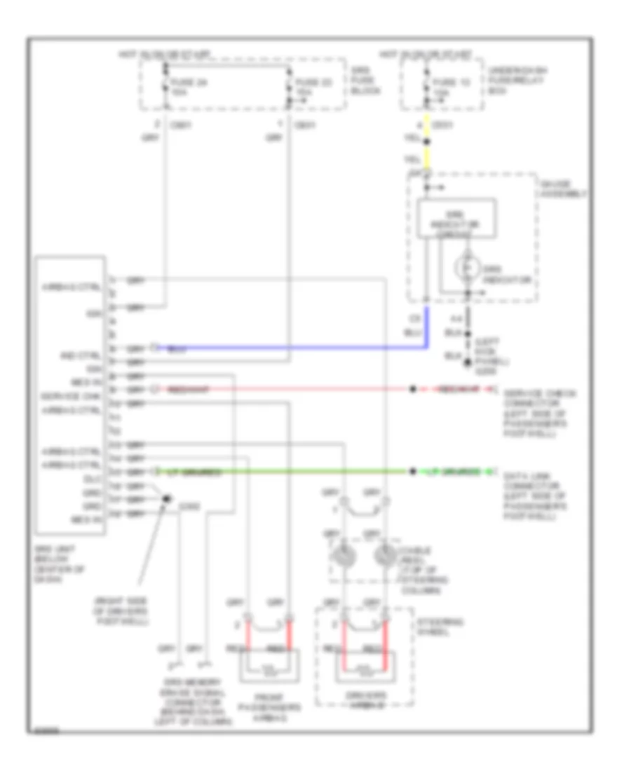
SUPPLEMENTAL RESTRAINTS
Supplemental Restraint Wiring Diagram for Honda Prelude 1997
List of elements for Supplemental Restraint Wiring Diagram for Honda Prelude 1997:

AIR CONDITIONINGANTI-THEFTANTI-LOCK BRAKESBODY COMPUTERENGINE PERFORMANCEHORNCOMPUTER DATA LINESEXTERIOR LIGHTSDEFOGGERSGROUND DISTRIBUTIONCOOLING FANHEADLIGHTSINSTRUMENT CLUSTERCRUISE CONTROLPOWER MIRRORSPOWER DOOR LOCKSRADIOPOWER DISTRIBUTIONINTERIOR LIGHTSSHIFT INTERLOCKSPOWER WINDOWSPOWER SEATSPOWER TOP/SUNROOFSUPPLEMENTAL RESTRAINTSSTARTING/CHARGINGWARNING SYSTEMSTRANSMISSIONWIPER/WASHER