Čeština
 Dansk
Dansk Deutsch
 Ελληνικά
 English
 Español
 Suomi
Suomi Français
 Français
 עברית
עברית Hrvatski
 Magyar
 Italiano
 日本語
日本語 한국어
한국어 Nederlands
 Polski
 Português
 Português
 Română
 Русский
 Slovenčina
 Slovenščina
 Svenska
 Türkçe
 中文 (中国)

SUPPLEMENTAL RESTRAINTS
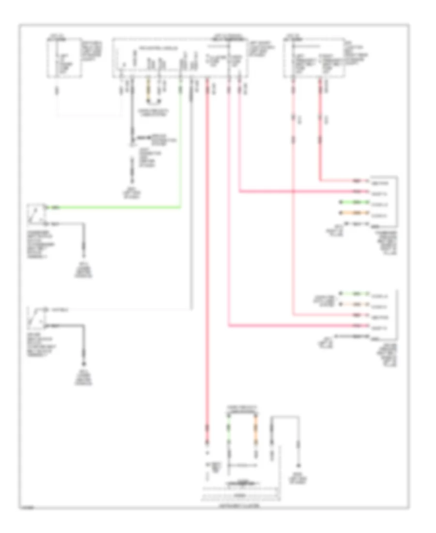
Air Bag Wiring Diagram (1 of 3) for Hyundai Equus Ultimate 2014


List of elements for Air Bag Wiring Diagram (1 of 3) for Hyundai Equus Ultimate 2014:
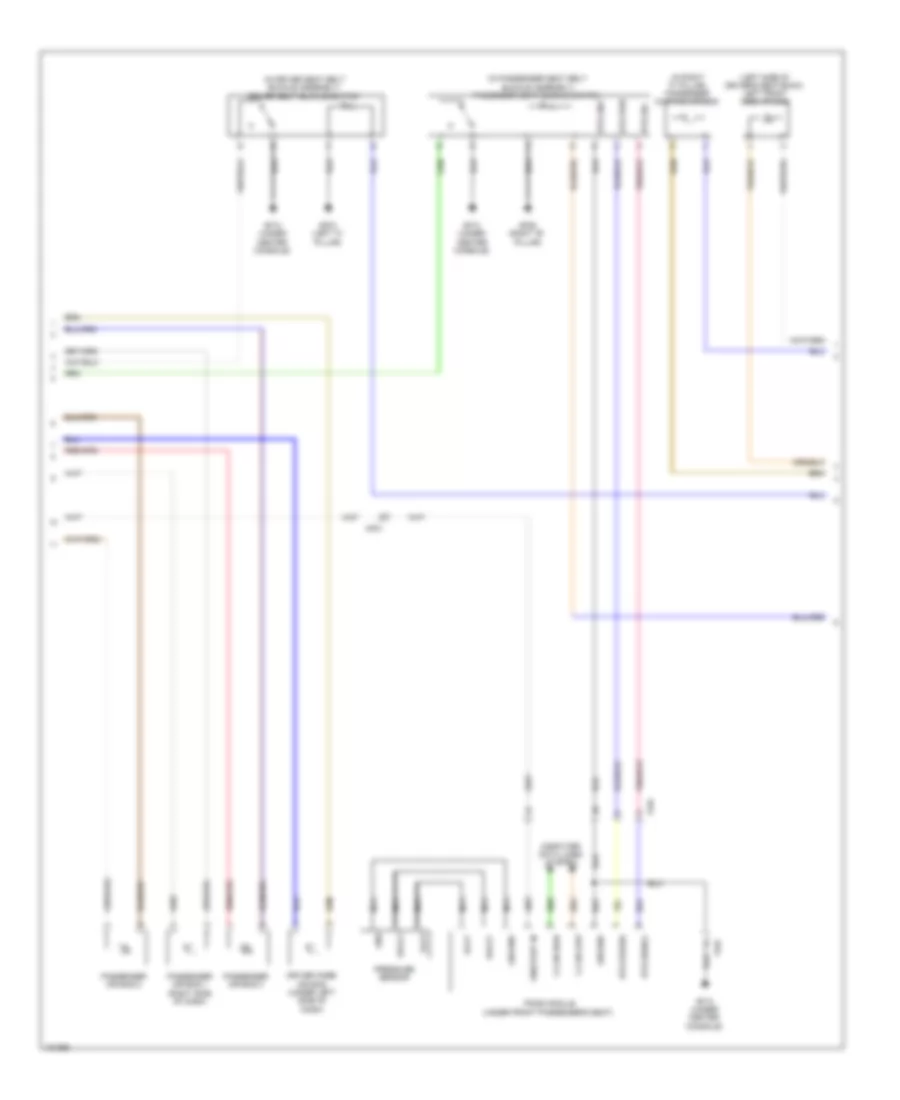
Air Bag Wiring Diagram (2 of 3) for Hyundai Equus Ultimate 2014
List of elements for Air Bag Wiring Diagram (2 of 3) for Hyundai Equus Ultimate 2014:
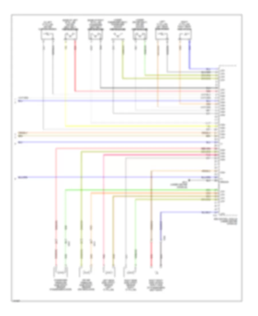
Air Bag Wiring Diagram (3 of 3) for Hyundai Equus Ultimate 2014
List of elements for Air Bag Wiring Diagram (3 of 3) for Hyundai Equus Ultimate 2014:
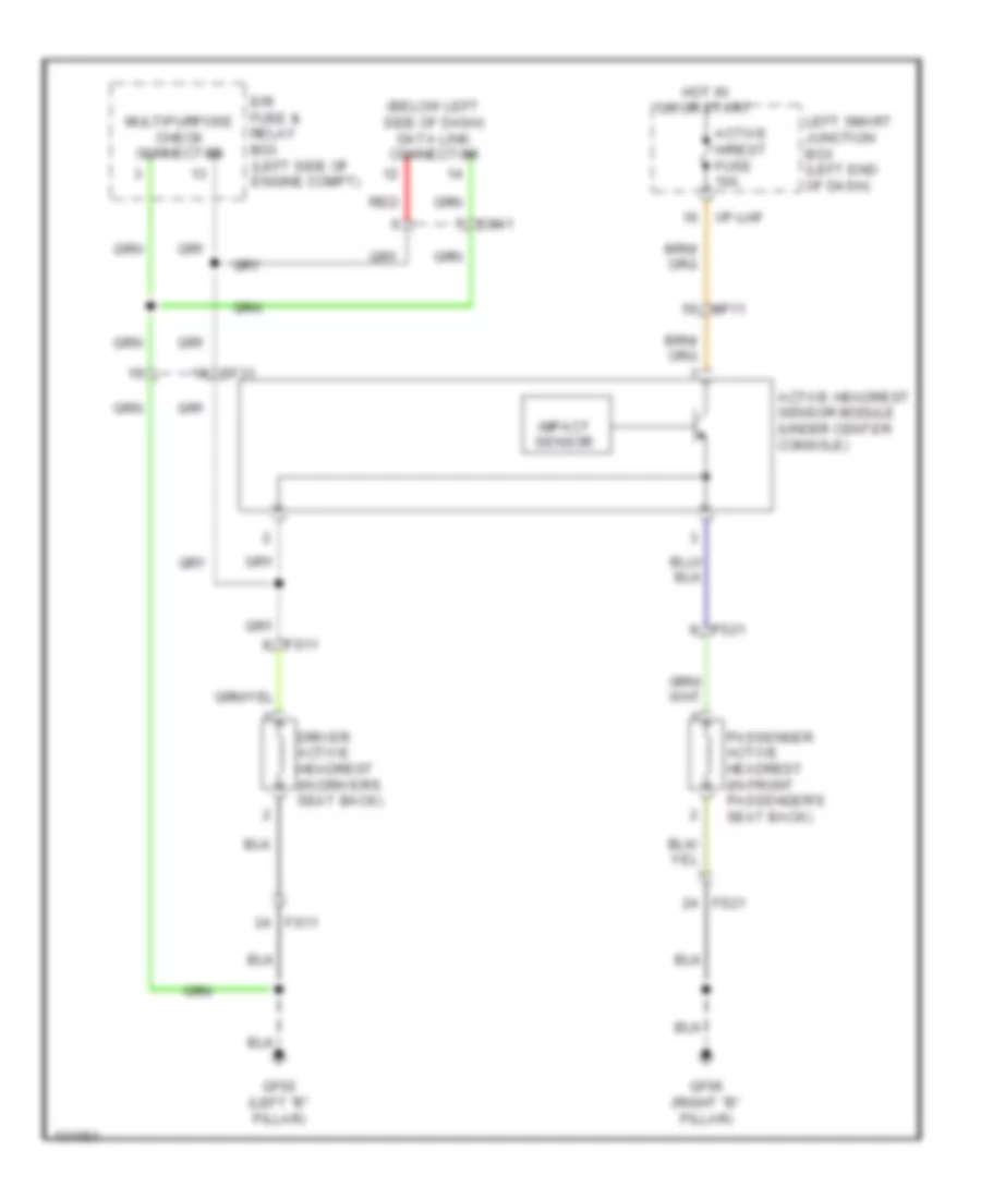
Electronic Active Headrest Wiring Diagram for Hyundai Equus Ultimate 2014
List of elements for Electronic Active Headrest Wiring Diagram for Hyundai Equus Ultimate 2014:
Pre-Safe Seat Belt Wiring Diagram for Hyundai Equus Ultimate 2014
List of elements for Pre-Safe Seat Belt Wiring Diagram for Hyundai Equus Ultimate 2014: