SUPPLEMENTAL RESTRAINTS
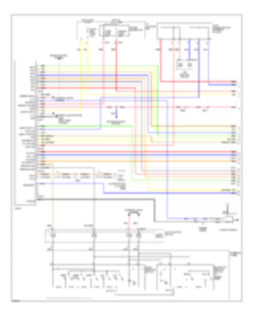
Supplemental Restraint Wiring Diagram for Hyundai XG350 2002
List of elements for Supplemental Restraint Wiring Diagram for Hyundai XG350 2002:
- (+)
- (-)
- (w/ hands- free)
- 5v (or vdd)
- A/c control module
- Acc/on input
- Air conditioning system
- Amp remote
- Antenna
- Audio
- Audio (-) remocon switch
- Audio fuse 15a
- Audio/ escl fuse 7.5a
- Aux detect
- Aux gnd
- Aux l in
- Aux r in
- B/t in
- B/t out
- Call
- Can high
- Can low
- Circuit
- Clock spring
- Cruise control system
- Down
- Ee11
- Em51
- End
- Eq select
- F/cable
- Feeder cable
- Fr(+)
- Fr(-)
- Glass antenna
- Gm05 (right side of dash)
- Gnd
- Hot at all times
- Hot in acc or on
- I/p junction box
- I/p-a
- I/p-b
- Ill ind
- Ill(+)
- Ill(-)
- Interior lights system
- Joint connector jm07 (steering column)
- M03-a
- M03-b
- M03-c1
- M03-c2
- M03-c3
- M07-b
- M48-r
- Memory fuse 10a
- Memory power
- Mf31
- Mic(+)
- Mic(-)
- Mode
- Mr01
- Multifunction switch
- Nca
- Pnk
- Power connector
- Red
- Remocon gnd
- Remocon sig
- Rl(+)
- Rl(-)
- Rr(+)
- Rr(-)
- Seek
- Speed signal
- Steering wheel
- Temp
- Usb d+ ipod rx
- Usb d-/ipod tx
- Vol
 Čeština
 Dansk
Dansk Deutsch
 Ελληνικά
 English
 Español
 Suomi
Suomi Français
 Français
 עברית
עברית Hrvatski
 Magyar
 Italiano
 日本語
日本語 한국어
한국어 Nederlands
 Polski
 Português
 Português
 Română
 Русский
 Slovenčina
 Slovenščina
 Svenska
 Türkçe
 中文 (中国)
 English