SUPPLEMENTAL RESTRAINTS
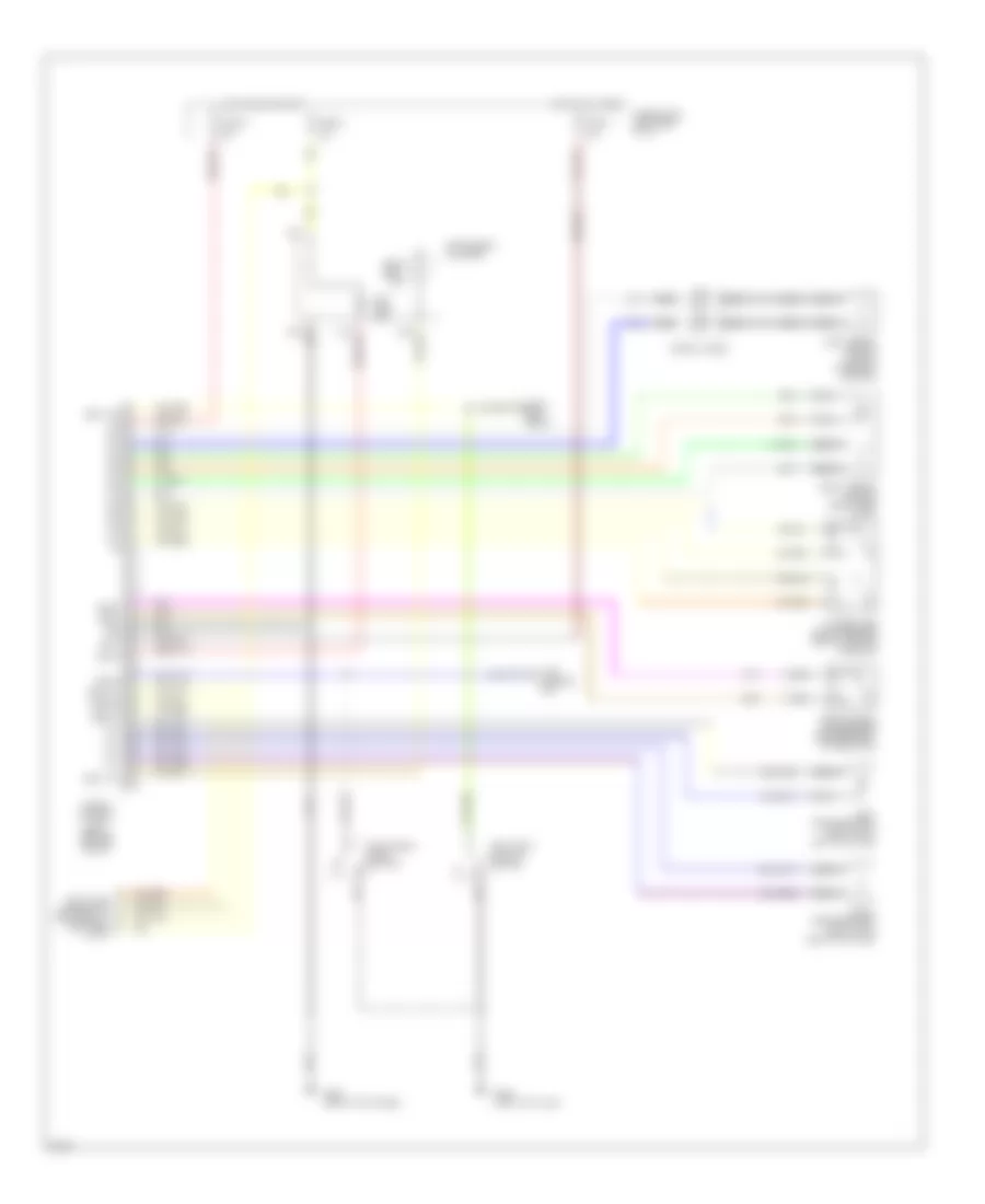
Supplemental Restraint Wiring Diagram for Infiniti G20 1994
List of elements for Supplemental Restraint Wiring Diagram for Infiniti G20 1994:
- 10a
- Air bag ind.
- Airbag control unit (below center of i/p)
- B-17
- Bat+
- Belt sw
- Belt w/l
- Czsc+
- Czsc-
- Data link connector for consult (left side of i/p)
- Dr sw
- Front crash zone sensor (center front of radiator)
- Fuse block (left side of i/p)
- Fuse h
- Fuse u
- Fuse y
- G203 (right kick panel)
- G308 (left "b" pillar)
- Gnd
- Hot at all times
- Hot in on or start
- Ign
- Ind lp
- Instrument cluster
- Left airbag module (top of steering column)
- Left front door switch
- Left pretensioner (bottom of left "b" pillar)
- Nca
- P/t+
- P/t-
- Right airbag module (right side of i/p)
- Right pretensioner (bottom of right "b" pillar)
- Seat belt buckle switch
- Seat belt ind.
- Seat belt relay
- Spiral cable
- Sq+
- Sq-
- Ss+
- Ss-
- Sss clk
- Sss rx
- Sss tx
- Time control unit
- Ts+
- Ts-
- Tunnel and safing sensor (below center console)
 Čeština
 Dansk
Dansk Deutsch
 Ελληνικά
 English
 Español
 Suomi
Suomi Français
 Français
 עברית
עברית Hrvatski
 Magyar
 Italiano
 日本語
日本語 한국어
한국어 Nederlands
 Polski
 Português
 Português
 Română
 Русский
 Slovenčina
 Slovenščina
 Svenska
 Türkçe
 中文 (中国)
 English