SUPPLEMENTAL RESTRAINTS
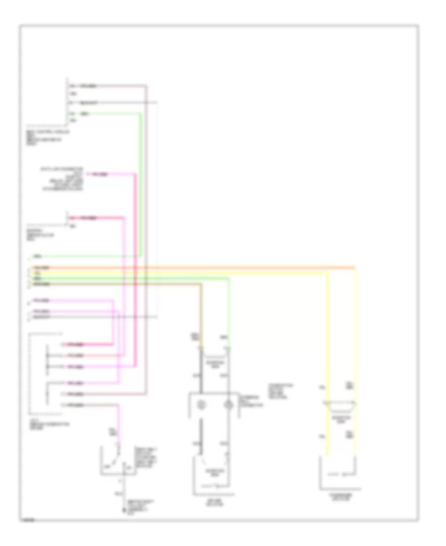
Supplemental Restraints Wiring Diagram (1 of 2) for Suzuki XL-7 Limited 2003
 https://portal-diagnostov.com/license.html
Automotive Electricians Portal FZCO
Automotive Electricians Portal FZCO
https://portal-diagnostov.com/license.html
https://portal-diagnostov.com/license.html
Automotive Electricians Portal FZCO
Automotive Electricians Portal FZCO
List of elements for Supplemental Restraints Wiring Diagram (1 of 2) for Suzuki XL-7 Limited 2003:
- (partial) (behind lower left side of dash)
- (under center console) g11
- A/b control module (behind lower center of dash)
- A/b diagnosis connector
- Air bag
- Air bag fuse 41 15a
- Combination meter
- Connection detection pin
- Cpu
- Fuse box (at lower left side of dash)
- G11
- Hot at all times
- Hot in on or start
- J/c (above glove box)
- J/c 3 (behind left side of dash)
- Left forward sensor (at left front of engine compartment)
- Left pretensioner
- Meter fuse 43 10a
- Note: shorting bars on a/b control module harness connector close when module is disconnected from harness. shorting bars connect pins: 5-6, 7-8, 9-10 & 11-12
- Pnk
- Radio dome fuse 35 15a
- Right forward sensor (at right front of engine compartment)
- Right pretensioner
- Seat belt
- Shorting bar
Supplemental Restraints Wiring Diagram (2 of 2) for Suzuki XL-7 Limited 2003
List of elements for Supplemental Restraints Wiring Diagram (2 of 2) for Suzuki XL-7 Limited 2003:
- (behind right taillight assembly) g12
- (partial) (below left side of dash, right of steering column)
- Body control module (bcm) (behind center of dash)
- Combination switch (driver inflator)
- Data link connector (dlc)
- Driver inflator
- E61
- Ecm/pcm (behind glove box)
- G54
- G55
- J/c 2 (behind combination meter)
- Nca
- Off
- Passenger inflator
- Seat belt switch (in driver seat belt buckle)
- Shorting bar
- Steering roll connector

 Čeština
 Dansk
Dansk Deutsch
 Ελληνικά
 English
 Español
 Suomi
Suomi Français
 Français
 עברית
עברית Hrvatski
 Magyar
 Italiano
 日本語
日本語 한국어
한국어 Nederlands
 Polski
 Português
 Português
 Română
 Русский
 Slovenčina
 Slovenščina
 Svenska
 Türkçe
 中文 (中国)