SUPPLEMENTAL RESTRAINTS
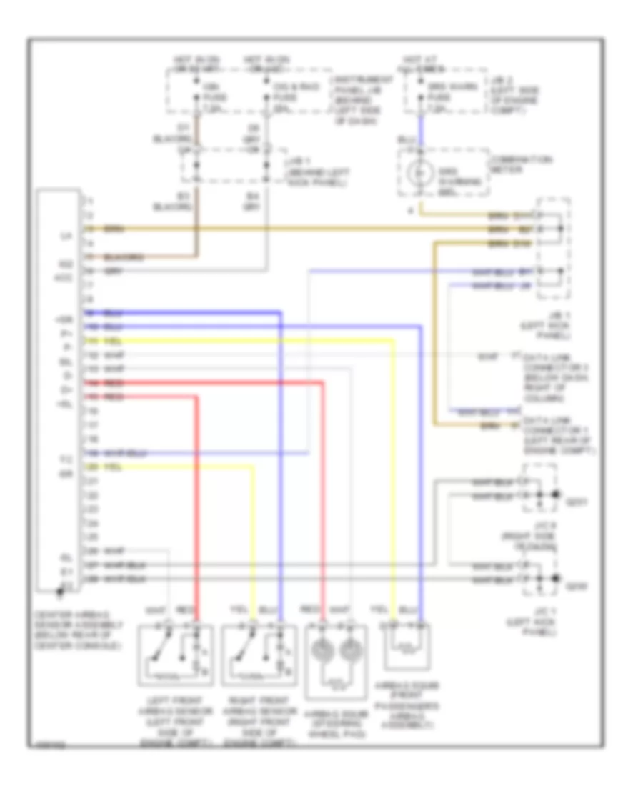
Supplemental Restraint Wiring Diagram for Toyota Celica GT 1998
List of elements for Supplemental Restraint Wiring Diagram for Toyota Celica GT 1998:
- (left front side of engine compt)
- (right front side of engine compt)
- +sl
- +sr
- -sl
- -sr
- Acc
- Airbag squib (front
- Airbag squib (steering wheel pad)
- Center airbag sensor assembly (below rear of center console)
- Cig & rad fuse 15a
- Combination meter
- D10
- D11
- Data link connector 1 (left rear of engine compt)
- Data link connector 3 (below dash, right of column)
- G200
- G201
- Hot at all times
- Hot in on or acc
- Hot in on or start
- Ig2
- Ign fuse 7.5a
- Instrument panel j/b (behind left side of dash)
- J/b 1 (behind left kick panel)
- J/b 1 (left kick panel)
- J/b 2 (left side of engine compt)
- J/c 1 (left kick panel)
- J/c 9 (right side of dash)
- Left front airbag sensor
- Passenger's airbag assembly)
- Red
- Right front airbag sensor
- Sil
- Srs warn fuse 7.5a
- Srs warning ind
 Čeština
 Dansk
Dansk Deutsch
 Ελληνικά
 English
 Español
 Suomi
Suomi Français
 Français
 עברית
עברית Hrvatski
 Magyar
 Italiano
 日本語
日本語 한국어
한국어 Nederlands
 Polski
 Português
 Português
 Română
 Русский
 Slovenčina
 Slovenščina
 Svenska
 Türkçe
 中文 (中国)
 English