SUPPLEMENTAL RESTRAINTS
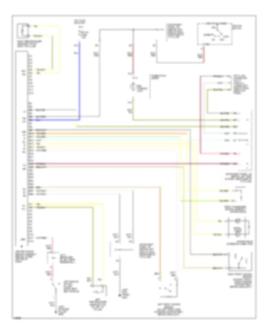
Supplemental Restraint Wiring Diagram for Toyota ECHO 2000
List of elements for Supplemental Restraint Wiring Diagram for Toyota ECHO 2000:
- (left kick panel) g200
- (left quarter pillar) g999
- +sl
- +sr
- -sl
- -sr
- A10
- A11
- A12
- A14
- Acc
- Air bag squib (steering wheel pad)
- Am2
- B10
- B11
- B12
- B13
- B14
- B15
- B16
- B17
- B18
- B19
- B20
- B21
- B22
- B23
- B24
- B25
- B26
- B27
- B28
- C10
- C11
- C12
- Center air bag sensor assembly (behind lower center of dash)
- Combination meter
- D10
- Data link connector (dlc) 3 (partial) (under left side of dash, near kick panel)
- Ecu-ig fuse 7.5a
- Front passenger air bag assembly air bag squib
- Hot at all times
- Hot in on or start
- Ig1
- Ig2
- Ignition switch
- Instrument panel j/b (behind left side of dash, near base of "a" pillar)
- J/c 11 (rearward of left rear fenderwell)
- Lbe+
- Left buckle switch (in left front seat belt buckle)
- Left front air bag sensor (on left front side of engine compartment, behind headlight)
- Left pretensioner (near bottom of left "b" pillar)
- Lock
- Pl+
- Pl-
- Pr+
- Pr-
- Right front air bag sensor (on right front side of engine compartment, behind headlight)
- Right pretensioner (near bottom of right "b" pillar)
- Sil
- Spiral cable
- Srs warning light
- Start
 Čeština
 Dansk
Dansk Deutsch
 Ελληνικά
 English
 Español
 Suomi
Suomi Français
 Français
 עברית
עברית Hrvatski
 Magyar
 Italiano
 日本語
日本語 한국어
한국어 Nederlands
 Polski
 Português
 Português
 Română
 Русский
 Slovenčina
 Slovenščina
 Svenska
 Türkçe
 中文 (中国)
 English