SUPPLEMENTAL RESTRAINTS
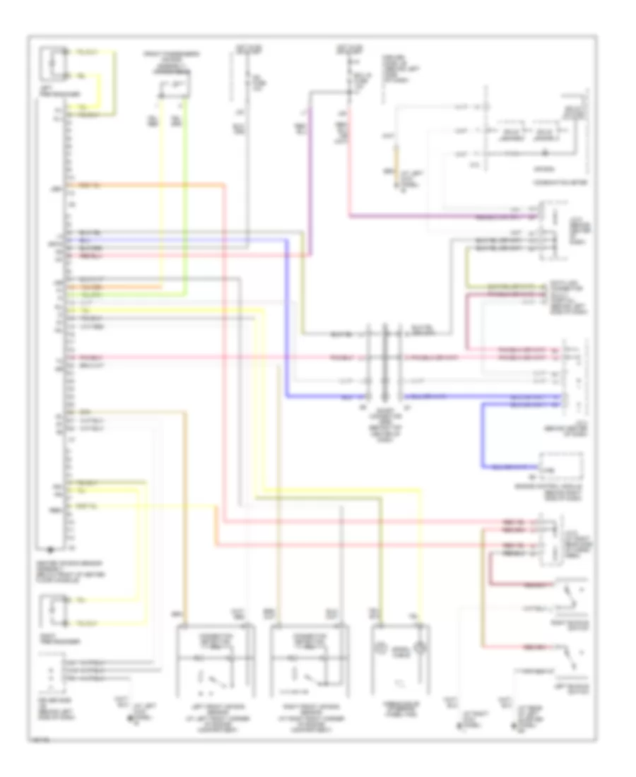
Supplemental Restraints Wiring Diagram for Toyota RAV4 2003
List of elements for Supplemental Restraints Wiring Diagram for Toyota RAV4 2003:
- (at left kick panel) ie
- (at rear of left quarter panel) bk
- (at right kick panel) ii
- (front passenger's air bag assembly) air bag squib
- (partial) (behind left side of dash)
- +sl
- +sr
- -sl
- -sr
- Air bag
- Airbag squib (steering wheel pad)
- C13
- Center air bag sensor assembly (below front of center floor console)
- Combination meter
- Connection detection pin
- Data link connector (dlc) 3
- Driver side j/b (behind left side of dash)
- Ecu ig fuse 10a
- Engine control module (behind right side of dash)
- F/ps
- Gsw2
- Hot in on or start
- Ig1
- Ig2
- Ig2 fuse 10a
- J/c 4 (behind center of dash)
- J/c 5 (behind center of dash)
- J/c 9 (at right rear side of cargo area)
- J28
- L19
- L20
- Lbe+
- Left buckle switch
- Left front air bag sensor (at left front corner of engine compartment)
- Left pretensioner
- Pl+
- Pl-
- Pr+
- Pr-
- Rbe+
- Right buckle switch
- Right front air bag sensor (at right front corner of engine compartment)
- Right pretensioner
- Short connector (srs) (behind top center of dash)
- Sil
- Solid state
- Spiral cable
 Čeština
 Dansk
Dansk Deutsch
 Ελληνικά
 English
 English
 Español
 Suomi
Suomi Français
 Français
 עברית
עברית Magyar
 Italiano
 日本語
日本語 한국어
한국어 Nederlands
 Polski
 Português
 Português
 Română
 Русский
 Slovenčina
 Slovenščina
 Svenska
 Türkçe
 中文 (中国)
 Hrvatski