TRANSMISSION
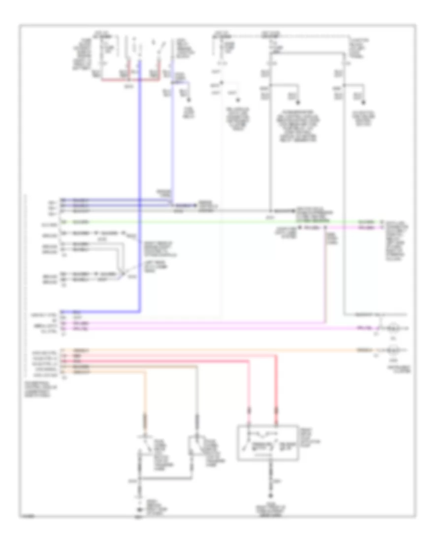
A/T Wiring Diagram for Chevrolet Tracker 2004
 https://portal-diagnostov.com/license.html
Automotive Electricians Portal FZCO
Automotive Electricians Portal FZCO
https://portal-diagnostov.com/license.html
https://portal-diagnostov.com/license.html
Automotive Electricians Portal FZCO
Automotive Electricians Portal FZCO
List of elements for A/T Wiring Diagram for Chevrolet Tracker 2004:
- (beside junction block) main relay
- (dash harn)
- (engine harn)
- (left rear of cylinder head)
- (on intake manifold) g103
- (rear of left cylinder head) engine coolant temperature (ect) sensor
- 4wd low sig
- A/c switch, main cruise control switch
- Accelerometer, drl control module, remote control door lock receiver, fuel pump relay, a/c comp control module, o2 heater relay, generator
- Automatic transmission
- Brake sw
- Computer data lines system
- Data link connector (dlc) obd ii (partial) (below left side of dash, right of steering column)
- Dlc gnd
- Dome fuse 10a
- Drl module, data link connector, instrument cluster, radio
- Ect in
- Engine controls system
- Exterior lights system
- Exterior lights system (hazard switch)
- Exterior lights system,
- F1 fuse 15a
- Four wheel drive low switch (top of transfer case)
- Fuel pump relay
- Fuse block (on right side of engine compt, in front of battery)
- G102
- G201
- Ground
- Harn)
- Hi a/t iss
- Hi a/t oss
- Horn relay
- Hot at all times
- Hot in on & start
- Ig fuse 20a
- Ign +
- Ignition coils, noise suppressor filter, heated oxygen sensors
- Input shaft speed sensor (left front of trans)
- Instrument cluster
- Instrument cluster, cruise control system (speed signal)
- Junction block (in left kick panel)
- Low a/t iss
- Low a/t oss
- Main rly ctrl
- Mil
- Mil ctrl
- Nca
- O/d ind
- O/d signal
- Od/off
- Output shaft speed sensor (lower right rear of trans)
- Over- drive switch
- P/n ind
- Power
- Powertrain control module (under right side of dash)
- Red
- S100
- S101
- S102
- S106
- S107
- S108
- S109
- S110
- S117
- S205
- S211
- S213
- S218
- S219
- S220
- S241
- S250
- S260
- Serial data
- Shield
- Shift interlock system
- Shift mode
- Shift program switch
- Shift sol 1
- Shift sol 2
- Shift solenoid
- Sp201 (behind right side of dash)
- Stop fuse 15a
- Stoplamp switch (above brake pedal)
- Tcc sol ctrl
- Throttle position (tp) sensor (on throttle assembly)
- Torque converter clutch solenoid
- Tp sens
- Tp sens gnd
- Tp sens ref
- Tr 2 pos
- Tr d pos
- Tr l pos
- Tr n pos
- Tr p pos
- Tr r pos
- Transmission range switch (right side of transmission)
- Turn fuse 10a
- Vehicle speed sensor (vss) (right side of transmission)
- Vss hi
Transfer Case Wiring Diagram for Chevrolet Tracker 2004
List of elements for Transfer Case Wiring Diagram for Chevrolet Tracker 2004:
- (engine harn)
- (left rear of cylinder head)
- (right rear of engine compt, mounted to intake manifold)
- 4wd
- 4wd ind ctrl
- 4wd low sig
- 4wd signal
- A/c switch, main cruise control switch
- Accelerometer, drl control module, remote control door lock receiver, fuel pump relay, a/c comp control module, o2 heater relay, generator
- Axle ctrl hi
- Axle ctrl lo
- Computer data lines system
- Data link connector (dlc) obd ii (partial) (below left side of dash, right of steering column)
- Dlc gnd
- Dome fuse 10a
- Drl module, data link connector, instrument cluster, radio
- Engine controls system
- F1 fuse 15a
- Four wheel drive low switch (top of transfer case)
- Four wheel drive switch (top of transfer case)
- Front drive axle actuator pump
- Fuel pump relay
- Fuse block (on right side of engine compt, in front of battery)
- G102
- G103
- G105 (right front of core support, near horn)
- G201
- Ground
- Hot at all times
- Hot in on or start
- Ig fuse 20a
- Ign +
- Ignition coils, noise suppressor filter, heated oxygen sensors
- Instrument cluster
- Junction block (in left kick panel)
- Main relay (beside junction block)
- Main rly ctrl
- Mil
- Mil ctrl
- Pnk
- Powertrain control module (under right side of dash)
- Pressure switch
- Red
- Release valve
- S100
- S101
- S102
- S105
- S107
- S201
- S205
- S218
- S219
- S250
- S260 (dash harn)
- Serial data
- Sp201 (behind right side of dash)

 Čeština
 Dansk
Dansk Deutsch
 Ελληνικά
 English
 Español
 Suomi
Suomi Français
 Français
 עברית
עברית Hrvatski
 Magyar
 Italiano
 日本語
日本語 한국어
한국어 Nederlands
 Polski
 Português
 Português
 Română
 Русский
 Slovenčina
 Slovenščina
 Svenska
 Türkçe
 中文 (中国)