TRANSMISSION
3.9L
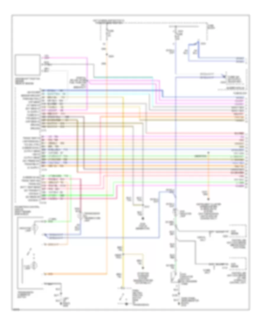
3.9L, Transmission Wiring Diagram (1 of 2) for Dodge Dakota 1996
 https://portal-diagnostov.com/license.html
Automotive Electricians Portal FZCO
Automotive Electricians Portal FZCO
https://portal-diagnostov.com/license.html
https://portal-diagnostov.com/license.html
Automotive Electricians Portal FZCO
Automotive Electricians Portal FZCO
List of elements for 3.9L, Transmission Wiring Diagram (1 of 2) for Dodge Dakota 1996:
- (dash panel, near resistor block) g123
- (left of radio) g206
- (near pcm)
- (partial splice; after fuel injector no.1 breakout)
- 4wd indicator lamp
- 4wd indicator switch (on transfer case)
- 4wd sense
- A14
- A15
- A16
- A17
- A21
- A22
- A23
- A27
- A31
- A32
- B11
- B21
- B25
- B27
- B28
- B29
- B30
- B31
- Batt temp sens
- Buzzer module
- C118
- C13
- C15
- C173
- C174
- C175
- C202
- C234
- C27
- C28
- C29
- C30
- Ccd bus +
- Ccd bus -
- Ckp sens
- Controller anti-lock brake (at abs hydraulic control unit)
- Controller anti-lock brake (behind right kick panel
- Crankshaft position sensor (rear of engine)
- D20
- D21
- Ect sens in
- Fuse 4a
- Fuse 5a
- Fuse block
- Fused b (+)
- Fused ign sw output (run/start) c234
- G107
- G125 (top of generator)
- G14
- Gov press sig
- Ground
- Hot w/headlamp switch in park or head position
- Iat sens in
- Ign power
- Illum. lamp
- Indicator lamp
- Instrument cluster (speedometer) & headlights system (daytime running lights module) (canada only)
- K118
- K21
- K22
- K24
- K54
- Map sens in
- Output sens
- Overdrive ind
- Overdrive sol
- Park/ neutral position switch (side of transmission)
- Park/neutral
- Pnk
- Powertrain control module (right fender side shield)
- S121
- S129
- S203
- S217
- Sci receive
- Sci transmit
- Sensor ground
- Starting/ charging system (engine starter motor relay)
- T13
- T14
- T18
- T25
- T30
- T33
- T41
- T54
- T59
- T60
- Tcc sol ctrl
- Tps sens in
- Trans od
- Trans relay
- Trans temp in
- Trans temp ind
- Transmission oil temperature lamp
- Transmission overdrive switch
- Var force sol
- Vss in
- W/abs only
- W/rwal only
- Z12
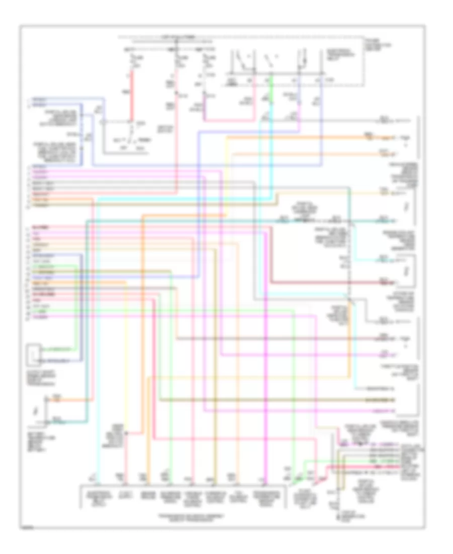
3.9L, Transmission Wiring Diagram (2 of 2) for Dodge Dakota 1996
List of elements for 3.9L, Transmission Wiring Diagram (2 of 2) for Dodge Dakota 1996:
- (bottom edge of knee bolster,
- (near park/ neutral position switch breakout)
- (not used)
- (partial splice;
- (partial splice; (near fuel injector no.7)
- (partial splice; near brake warning lamp switch breakout)
- (partial splice; near branch to airbag control module)
- (partial splice; near branch to airbag control module)
- (partial splice; near fuel injector no.6 breakout) (3.9l) or fuel injector no.8 breakout) (5.2l)
- (partial splice; near underhood lamp breakout
- (top of generator) g125
- Acc
- Battery temperature sensor (below battery)
- Between
- Breakouts for fuel injectors no.2 & no.4)
- C120
- C232
- D20
- D21
- Electronic transmission relay
- Electronic transmission relay output
- Engine coolant temperature sensor (near generator)
- Fuse b 30a
- Fuse c 40a
- Fuse d 30a
- Governor pressure signal
- Hot at all times
- Ignition switch
- Intake air temperature sensor (on intake manifold)
- Left of steering column)
- Manifold absolute pressure sensor (on throttle body)
- Off
- Output shaft speed sensor (side of transmission)
- Overdrive solenoid control
- Plant diagnostic connector (plant use only)
- Pnk
- Power distribution center
- Red
- Run
- S115
- S118
- S121
- Sensor ground
- Start
- Tcc solenoid control
- Throttle position sensor (on throttle body)
- Transmission solenoid assembly (side of transmission)
- Transmission temperature sensor signal
- Variable force solenoid control
- Vehicle speed sensor (rear of transmission or transfer case)
- Z12
5.2L
5.2L, Transmission Wiring Diagram (1 of 2) for Dodge Dakota 1996
List of elements for 5.2L, Transmission Wiring Diagram (1 of 2) for Dodge Dakota 1996:
- (dash panel, near resistor block) g123
- (left of radio) g206
- (near pcm)
- (partial splice; after fuel injector no.1 breakout)
- 4wd indicator lamp
- 4wd indicator switch (on transfer case)
- 4wd sense
- A14
- A15
- A16
- A17
- A21
- A22
- A23
- A27
- A31
- A32
- B11
- B21
- B25
- B27
- B28
- B29
- B30
- B31
- Batt temp sens
- Buzzer module
- C118
- C13
- C15
- C173
- C174
- C175
- C202
- C234
- C27
- C28
- C29
- C30
- Ccd bus +
- Ccd bus -
- Ckp sens
- Controller anti-lock brake (at abs hydraulic control unit)
- Controller anti-lock brake (behind right kick panel
- Crankshaft position sensor (rear of engine)
- D20
- D21
- Ect sens in
- Fuse 4a
- Fuse 5a
- Fuse block
- Fused b (+)
- Fused ign sw output (run/start) c234
- G107
- G125 (top of generator)
- G14
- Gov press sig
- Ground
- Hot w/headlamp switch in park or head position
- Iat sens in
- Ign power
- Illum. lamp
- Indicator lamp
- Instrument cluster (speedometer) & headlights system (daytime running lights module) (canada only)
- K118
- K21
- K22
- K24
- K54
- Map sens in
- Output sens
- Overdrive ind
- Overdrive sol
- Park/ neutral position switch (side of transmission)
- Park/neutral
- Pnk
- Powertrain control module (right fender side shield)
- S121
- S129
- S203
- S217
- Sci receive
- Sci transmit
- Sensor ground
- Starting/ charging system (engine starter motor relay)
- T13
- T14
- T18
- T25
- T30
- T33
- T41
- T54
- T59
- T60
- Tcc sol ctrl
- Tps sens in
- Trans od
- Trans relay
- Trans temp in
- Trans temp ind
- Transmission oil temperature lamp
- Transmission overdrive switch
- Var force sol
- Vss in
- W/abs only
- W/rwal only
- Z12
5.2L, Transmission Wiring Diagram (2 of 2) for Dodge Dakota 1996
List of elements for 5.2L, Transmission Wiring Diagram (2 of 2) for Dodge Dakota 1996:
- (bottom edge of knee bolster,
- (near park/ neutral position switch breakout)
- (not used)
- (partial splice;
- (partial splice; (near fuel injector no.7)
- (partial splice; near brake warning lamp switch breakout)
- (partial splice; near branch to airbag control module)
- (partial splice; near branch to airbag control module)
- (partial splice; near fuel injector no.6 breakout) (3.9l) or fuel injector no.8 breakout) (5.2l)
- (partial splice; near underhood lamp breakout
- (top of generator) g125
- Acc
- Battery temperature sensor (below battery)
- Between
- Breakouts for fuel injectors no.2 & no.4)
- C120
- C232
- D20
- D21
- Electronic transmission relay
- Electronic transmission relay output
- Engine coolant temperature sensor (near generator)
- Fuse b 30a
- Fuse c 40a
- Fuse d 30a
- Governor pressure signal
- Hot at all times
- Ignition switch
- Intake air temperature sensor (on intake manifold)
- Left of steering column)
- Manifold absolute pressure sensor (on throttle body)
- Off
- Output shaft speed sensor (side of transmission)
- Overdrive solenoid control
- Plant diagnostic connector (plant use only)
- Pnk
- Power distribution center
- Red
- Run
- S115
- S118
- S121
- Sensor ground
- Start
- Tcc solenoid control
- Throttle position sensor (on throttle body)
- Transmission solenoid assembly (side of transmission)
- Transmission temperature sensor signal
- Variable force solenoid control
- Vehicle speed sensor (rear of transmission or transfer case)
- Z12

 Čeština
 Dansk
Dansk Deutsch
 Ελληνικά
 English
 Español
 Suomi
Suomi Français
 Français
 עברית
עברית Hrvatski
 Magyar
 Italiano
 日本語
日本語 한국어
한국어 Nederlands
 Polski
 Português
 Português
 Română
 Русский
 Slovenčina
 Slovenščina
 Svenska
 Türkçe
 中文 (中国)