TRANSMISSION
5.4L
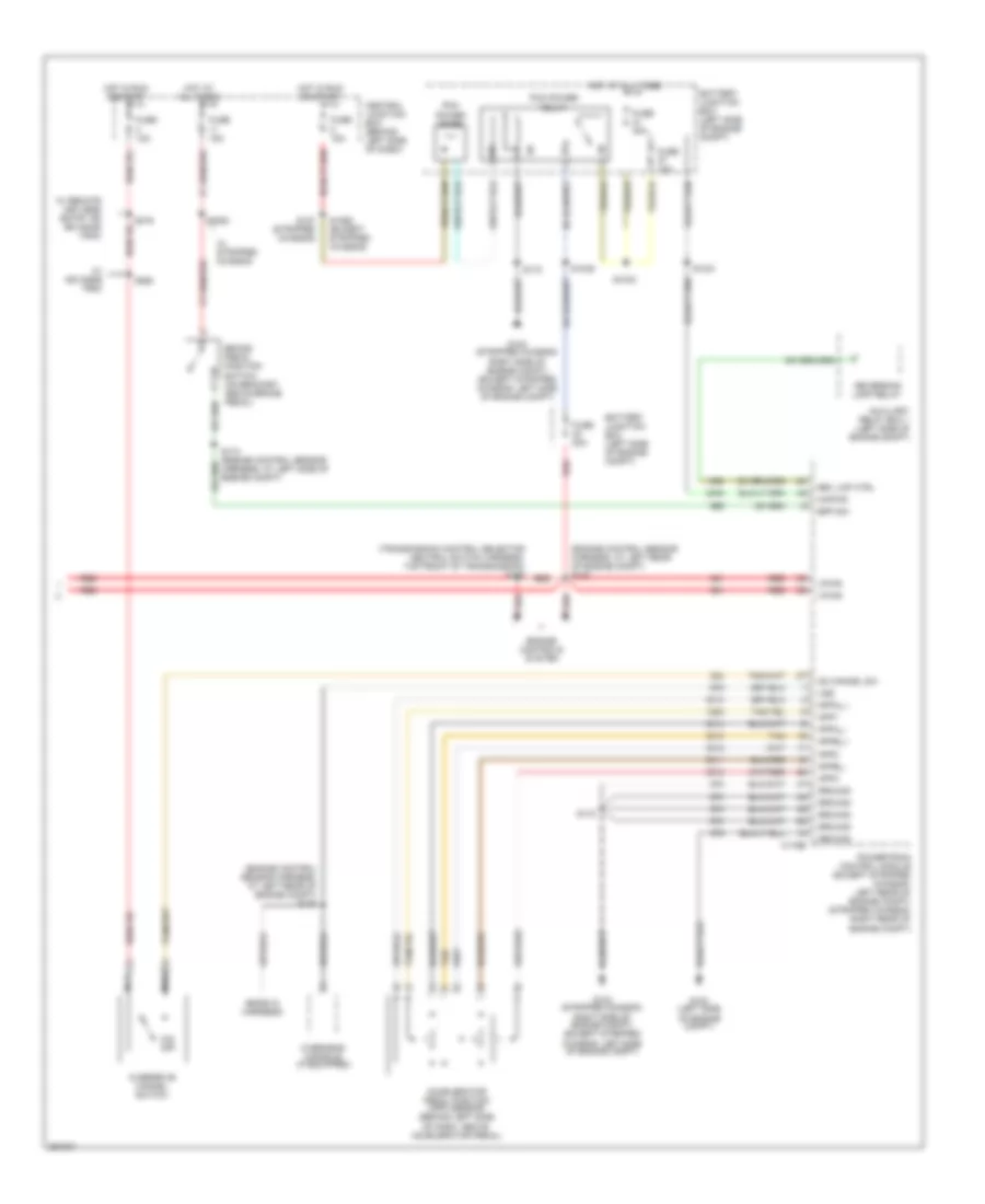
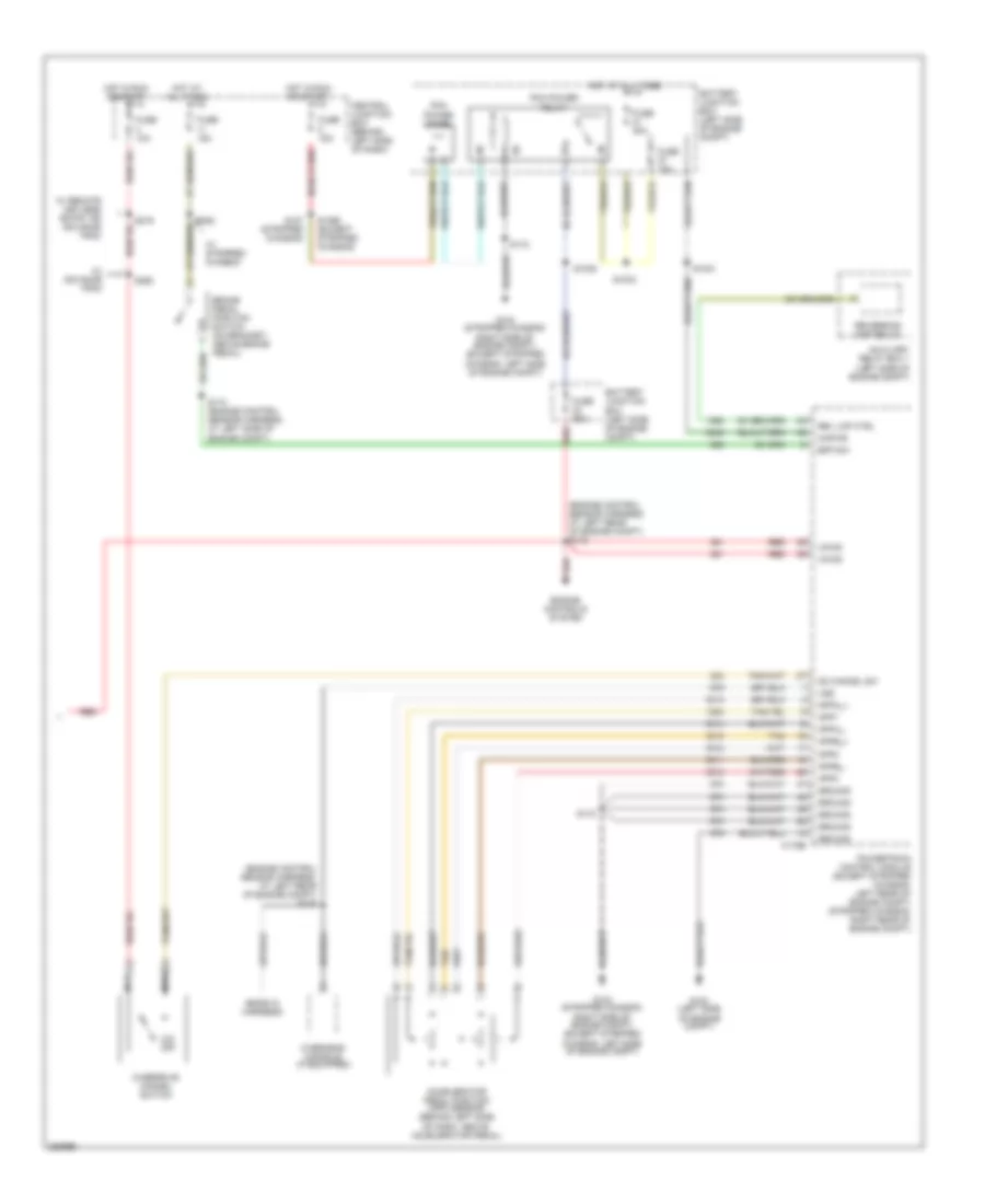
5.4L, A/T Wiring Diagram, with Torqshift (1 of 2) for Ford Cutaway E350 Super Duty 2007
 https://portal-diagnostov.com/license.html
Automotive Electricians Portal FZCO
Automotive Electricians Portal FZCO
https://portal-diagnostov.com/license.html
https://portal-diagnostov.com/license.html
Automotive Electricians Portal FZCO
Automotive Electricians Portal FZCO
List of elements for 5.4L, A/T Wiring Diagram, with Torqshift (1 of 2) for Ford Cutaway E350 Super Duty 2007:
- (engine control sensor & fuel charge harness, at rear of engine)
- (main harness, at left side of dash)
- (right rear of transmission) output shaft speed sensor
- (transmission control selector neutral switch harness, in breakout to right side of transmission)
- (transmission control selector neutral switch harness, near breakout to output shaft speed sensor
- (transmission control selector neutral switch harness, near breakout to speed sensor assembly)
- Brake pressure switch (left rear of engine compt)
- C175b
- C175e
- C175t
- C220a
- Can+
- Can-
- Data link connector (below left side of dash)
- Electronic throttle control motor (5.4l: top front of engine) (6.8l: top left side of engine)
- Engine controls system
- Feps
- G104 (stripped chassis: right side of engine compt) (except stripped chassis: left side of engine compt)
- Iat sensor
- Instrument cluster
- Intermediate shaft speed sensor
- Iss sensor
- Maf sensor
- Mass air flow (maf) sensor (at center of engine compt)
- Oss sensor
- Pc-a sol
- Powertrain control module (except stripped chassis: left rear of engine compt) (stripped chassis: right rear of engine compt)
- Pressure control (pc-a) solenoid
- Red
- S1037
- S123
- S136 (engine control sensor & fuel harness, at rear of engine)
- S139
- S172
- S198
- S228 (main harn, near breakout to inertia fuel shut off switch)
- S269
- Shift sol a
- Shift sol b
- Shift sol c
- Shift sol d
- Shift sol e
- Shift solenoid pressure control a (sspc-a)
- Shift solenoid pressure control b (sspc-b)
- Shift solenoid pressure control c (sspc-c)
- Shift solenoid pressure control d (sspc-d)
- Shift solenoid pressure control e (sspc-e)
- Sig return
- Signal return
- Speed sensor assembly (left side of transmission)
- Tcc sol
- Tft sensor
- Throttle position sensor (top of engine, near air intake)
- Throttle+
- Throttle-
- Torqshift transmission
- Torque converter clutch solenoid
- Tps pow
- Tps sig return
- Tps1 sig
- Tps2 sig
- Transmission fluid temperature sensor
- Transmission range sensor assembly (tr-p)
- Trs sensor
- Tss sensor
- Turbine shaft speed sensor
- Vpwr
- Vref
5.4L, A/T Wiring Diagram, with Torqshift (2 of 2) for Ford Cutaway E350 Super Duty 2007
List of elements for 5.4L, A/T Wiring Diagram, with Torqshift (2 of 2) for Ford Cutaway E350 Super Duty 2007:
- (ends in harness)
- (engine control sensor harness, at left rear of engine compt) s135
- (engine control sensor harness, at left rear of engine compt) s142
- Accelerator pedal position (app) sensor (behind left side of dash, above accelerator pedal)
- App1
- App2
- App3
- Appa_+
- Appa_-
- Appb_+
- Appb_-
- Auxiliary relay box 1 (left side of engine compt)
- Battery junction box (left side of engine compt)
- Bpp sw
- Brake pedal position switch (on bracket, above brake pedal)
- C175b
- Central junction box (behind left side of dash)
- Engine controls system
- Fuse 10a
- Fuse 15a
- Fuse 20a
- Fuse 30a
- G100 (left side of engine compt)
- G104 (stripped chassis: right side of engine compt) (except stripped chassis: left side of engine compt)
- Ground
- Hot at all times
- Hot in run or start
- Kapwr
- Nca
- O/d off
- Od cancel sw
- Overdrive cancel switch
- Overhead console (if equipped)
- Pcm power diode
- Pcm power relay
- Powertrain control module (except stripped chassis: left rear of engine compt) (stripped chassis: right rear of engine compt)
- Red
- Rev lmp ctrl
- Reversing lamp relay
- S1021
- S1033
- S1035
- S1065 (except stripped chassis)
- S127 (stripped chassis)
- S172
- S174 (engine control sensor harness, at left side of engine compt)
- S216
- S260
- S282
- Tan
- Vpwr
- Vss
- W/ advance trac
- W/ remote keyless entry or advance trac
- W/ stripped chassis
5.4L, A/T Wiring Diagram, without Torqshift (1 of 2) for Ford Cutaway E350 Super Duty 2007
List of elements for 5.4L, A/T Wiring Diagram, without Torqshift (1 of 2) for Ford Cutaway E350 Super Duty 2007:
- (at left side of transmission) digital transmission range (dtr) sensor
- (main harness, at left side of dash)
- 4.6l
- 4r75e transmission
- 5.4l
- C175b
- C175e
- C175t
- C220a
- Can+
- Can-
- Data link connector (below left side of dash)
- Dtr tr1
- Dtr tr2
- Dtr tr3a
- Dtr tr4
- Electronic pressure control solenoid
- Electronic throttle control motor (top front of engine)
- Engine controls system
- Epc sol
- Feps
- G104 (stripped chassis: right side of engine compt) (except stripped chassis: left side of engine compt)
- Iat sensor
- Instrument cluster
- Maf return
- Maf sensor
- Mass air flow (maf) sensor (at center of engine compt)
- Oss sig
- Output shaft speed (oss) sensor (left side of transmission)
- Powertrain control module (except stripped chassis: left rear of engine compt) (stripped chassis: right rear of engine compt)
- Red
- S136 (engine control sensor & fuel harness, at rear of engine)
- S172
- S198 (trans control selector neutral switch harness, on top of trans)
- S228 (main harness, near breakout to inertia fuel shutoff switch)
- S269
- Shift sol a
- Shift sol b
- Shift solenoids
- Sig return
- Tcc sol
- Tft sensor sig
- Throttle position sensor (top of engine, near air intake)
- Throttle+
- Throttle-
- Torque converter clutch solenoid
- Tps pow
- Tps sig return
- Tps1 sig
- Tps2 sig
- Transmission fluid temperature sensor
- Tss sensor
- Turbine shaft speed (tss) sensor (left side of transmission)
5.4L, A/T Wiring Diagram, without Torqshift (2 of 2) for Ford Cutaway E350 Super Duty 2007
List of elements for 5.4L, A/T Wiring Diagram, without Torqshift (2 of 2) for Ford Cutaway E350 Super Duty 2007:
- (ends in harness)
- (engine control sensor harness, at left rear of engine compt) s135
- (engine control sensor harness, at left rear of engine compt) s142
- (transmission control selector neutral switch harness, top front of transmission) s100
- Accelerator pedal position (app) sensor (behind left side of dash, above accelerator pedal)
- App1
- App2
- App3
- Appa_+
- Appa_-
- Appb_+
- Appb_-
- Auxiliary relay box 1 (left side of engine compt)
- Battery junction box (left side of engine compt)
- Bpp sw
- Brake pedal position switch (on bracket, above brake pedal)
- C175b
- Central junction box (behind left side of dash)
- Engine controls system
- Fuse 10a
- Fuse 15a
- Fuse 20a
- Fuse 30a
- G100 (left side of engine compt)
- G104 (stripped chassis: right side of engine compt) (except stripped chassis: left side of engine compt)
- Ground
- Hot at all times
- Hot in run or start
- Kapwr
- Nca
- O/d off
- Od cancel sw
- Overdrive cancel switch
- Overhead console (if equipped)
- Pcm power diode
- Pcm power relay
- Powertrain control module (except stripped chassis: left rear of engine compt) (stripped chassis: right rear of engine compt)
- Red
- Rev lmp ctrl
- Reversing lamp relay
- S1021
- S1033
- S1035
- S1065 (except stripped chassis)
- S127 (stripped chassis)
- S172
- S174 (engine control sensor harness, at left side of engine compt)
- S216
- S260
- S282
- Tan
- Vpwr
- Vss
- W/ advance trac
- W/ remote keyless entry or advance trac
- W/ stripped chassis
6.0L DIESEL
6.0L Diesel, A/T Wiring Diagram (1 of 2) for Ford Cutaway E350 Super Duty 2007
List of elements for 6.0L Diesel, A/T Wiring Diagram (1 of 2) for Ford Cutaway E350 Super Duty 2007:
- (ends in harness)
- (engine control sensor harn, at rear of engine compt)
- (engine control sensor harness, at left rear of engine) s135
- (left side of engine compt) g100
- (main harness, at left side of dash)
- (right front of engine compt) g107
- (window regulator relay switch harness, in breakout to accelerator pedal position switch)
- Accelerator pedal position sensor (behind left side of dash, above accelerator pedal)
- App2_sig
- App3_sig
- App_b+
- App_b-
- Battery junction box (right front of engine compt)
- Bpp
- Brake pedal position switch (on bracket, above brake pedal)
- C1381b
- C220a
- Can+
- Can-
- Central junction box (behind left side of dash)
- Data link connector (below left side of dash)
- Engine controls system
- Feps
- Fuse 10a
- Fuse 15a
- Fuse 30a
- G107 (right front of engine compt)
- Ground
- Hot at all times
- Hot in run or start
- Iat sensor
- Instrument cluster
- Kapwr
- Maf sensor
- Maf sensor rtn
- Mass air flow sensor (left front of engine compt)
- Od cancel
- Overhead console (if equipped)
- Pcm power diode
- Pcm power relay
- Powertrain control module (left rear of engine compt)
- Red
- S1033
- S1065
- S1068 (engine control sensor harn, at rear of engine compt)
- S136
- S138 (engine control sensor harn, in breakout to pcm)
- S142 (engine control red
- S172
- S174 (engine control sensor harness, at left rear of engine compt)
- S200
- S228 (main harness, near breakout to inertia fuel shut off switch)
- S269
- Sensor harn, at rear of engine compt)
- Sig rtn cowl
- Tan
- Vpwr
- Vref cowl
- Vss
6.0L Diesel, A/T Wiring Diagram (2 of 2) for Ford Cutaway E350 Super Duty 2007
List of elements for 6.0L Diesel, A/T Wiring Diagram (2 of 2) for Ford Cutaway E350 Super Duty 2007:
- (in trans control selector neutral switch harness, on top left side of transmission)
- (trans control selector neutral switch harness, in breakout to right side of transmission)
- Auxiliary relay box 1 (right front of engine compt)
- C1381t
- Central junction box (behind left side of dash)
- Fuse 10a
- Hot in run or start
- Intermediate shaft speed sensor
- Iss sig
- Nca
- Oss sig
- Output shaft speed sensor (at rear of transmission)
- Overdrive cancel switch
- Pc-a sol
- Powertrain control module (left rear of engine compt)
- Pressure control (pc-a) solenoid
- Rev lmp ctrl
- Reversing lamp relay
- S1037
- S198
- S215
- S260
- Shift solenoid pressure control a (sspc-a)
- Shift solenoid pressure control b (sspc-b)
- Shift solenoid pressure control c (sspc-c)
- Shift solenoid pressure control d (sspc-d)
- Shift solenoid pressure control e (sspc-e)
- Sig return
- Speed sensor assembly (left side of transmission)
- Sspc-a crl
- Sspc-b ctrl
- Sspc-c crl
- Sspc-d ctrl
- Sspc-e ctrl
- Tcc sol ctrl
- Tft sens sig
- Torqshift transmission (left side of transmission)
- Torque converter clutch solenoid
- Tr-p sig
- Transmission fluid temperature sensor
- Transmission range sensor assembly (tr-p)
- Tss sig
- Turbine shaft speed sensor
- Vpwr
- Vref
- W/ advance trac
- W/ remote keyless entry or advance trac
6.8L
6.8L, A/T Wiring Diagram (1 of 2) for Ford Cutaway E350 Super Duty 2007
List of elements for 6.8L, A/T Wiring Diagram (1 of 2) for Ford Cutaway E350 Super Duty 2007:
- (engine control sensor & fuel charge harness, at rear of engine)
- (main harness, at left side of dash)
- (right rear of transmission) output shaft speed sensor
- (transmission control selector neutral switch harness, in breakout to right side of transmission)
- (transmission control selector neutral switch harness, near breakout to output shaft speed sensor
- (transmission control selector neutral switch harness, near breakout to speed sensor assembly)
- Brake pressure switch (left rear of engine compt)
- C175b
- C175e
- C175t
- C220a
- Can+
- Can-
- Data link connector (below left side of dash)
- Electronic throttle control motor (5.4l: top front of engine) (6.8l: top left side of engine)
- Engine controls system
- Feps
- G104 (stripped chassis: right side of engine compt) (except stripped chassis: left side of engine compt)
- Iat sensor
- Instrument cluster
- Intermediate shaft speed sensor
- Iss sensor
- Maf sensor
- Mass air flow (maf) sensor (at center of engine compt)
- Oss sensor
- Pc-a sol
- Powertrain control module (except stripped chassis: left rear of engine compt) (stripped chassis: right rear of engine compt)
- Pressure control (pc-a) solenoid
- Red
- S1037
- S123
- S136 (engine control sensor & fuel harness, at rear of engine)
- S139
- S172
- S198
- S228 (main harn, near breakout to inertia fuel shut off switch)
- S269
- Shift sol a
- Shift sol b
- Shift sol c
- Shift sol d
- Shift sol e
- Shift solenoid pressure control a (sspc-a)
- Shift solenoid pressure control b (sspc-b)
- Shift solenoid pressure control c (sspc-c)
- Shift solenoid pressure control d (sspc-d)
- Shift solenoid pressure control e (sspc-e)
- Sig return
- Signal return
- Speed sensor assembly (left side of transmission)
- Tcc sol
- Tft sensor
- Throttle position sensor (top of engine, near air intake)
- Throttle+
- Throttle-
- Torqshift transmission
- Torque converter clutch solenoid
- Tps pow
- Tps sig return
- Tps1 sig
- Tps2 sig
- Transmission fluid temperature sensor
- Transmission range sensor assembly (tr-p)
- Trs sensor
- Tss sensor
- Turbine shaft speed sensor
- Vpwr
- Vref
6.8L, A/T Wiring Diagram (2 of 2) for Ford Cutaway E350 Super Duty 2007
List of elements for 6.8L, A/T Wiring Diagram (2 of 2) for Ford Cutaway E350 Super Duty 2007:
- (ends in harness)
- (engine control sensor harness, at left rear of engine compt) s135
- (engine control sensor harness, at left rear of engine compt) s142
- Accelerator pedal position (app) sensor (behind left side of dash, above accelerator pedal)
- App1
- App2
- App3
- Appa_+
- Appa_-
- Appb_+
- Appb_-
- Auxiliary relay box 1 (left side of engine compt)
- Battery junction box (left side of engine compt)
- Bpp sw
- Brake pedal position switch (on bracket, above brake pedal)
- C175b
- Central junction box (behind left side of dash)
- Engine controls system
- Fuse 10a
- Fuse 15a
- Fuse 20a
- Fuse 30a
- G100 (left side of engine compt)
- G104 (stripped chassis: right side of engine compt) (except stripped chassis: left side of engine compt)
- Ground
- Hot at all times
- Hot in run or start
- Kapwr
- Nca
- O/d off
- Od cancel sw
- Overdrive cancel switch
- Overhead console (if equipped)
- Pcm power diode
- Pcm power relay
- Powertrain control module (except stripped chassis: left rear of engine compt) (stripped chassis: right rear of engine compt)
- Red
- Rev lmp ctrl
- Reversing lamp relay
- S1021
- S1033
- S1035
- S1065 (except stripped chassis)
- S127 (stripped chassis)
- S172
- S174 (engine control sensor harness, at left side of engine compt)
- S216
- S260
- S282
- Tan
- Vpwr
- Vss
- W/ advance trac
- W/ remote keyless entry or advance trac
- W/ stripped chassis

 Čeština
 Dansk
Dansk Deutsch
 Ελληνικά
 English
 Español
 Suomi
Suomi Français
 Français
 עברית
עברית Hrvatski
 Magyar
 Italiano
 日本語
日本語 한국어
한국어 Nederlands
 Polski
 Português
 Português
 Română
 Русский
 Slovenčina
 Slovenščina
 Svenska
 Türkçe
 中文 (中国)