TRANSMISSION
4.0L
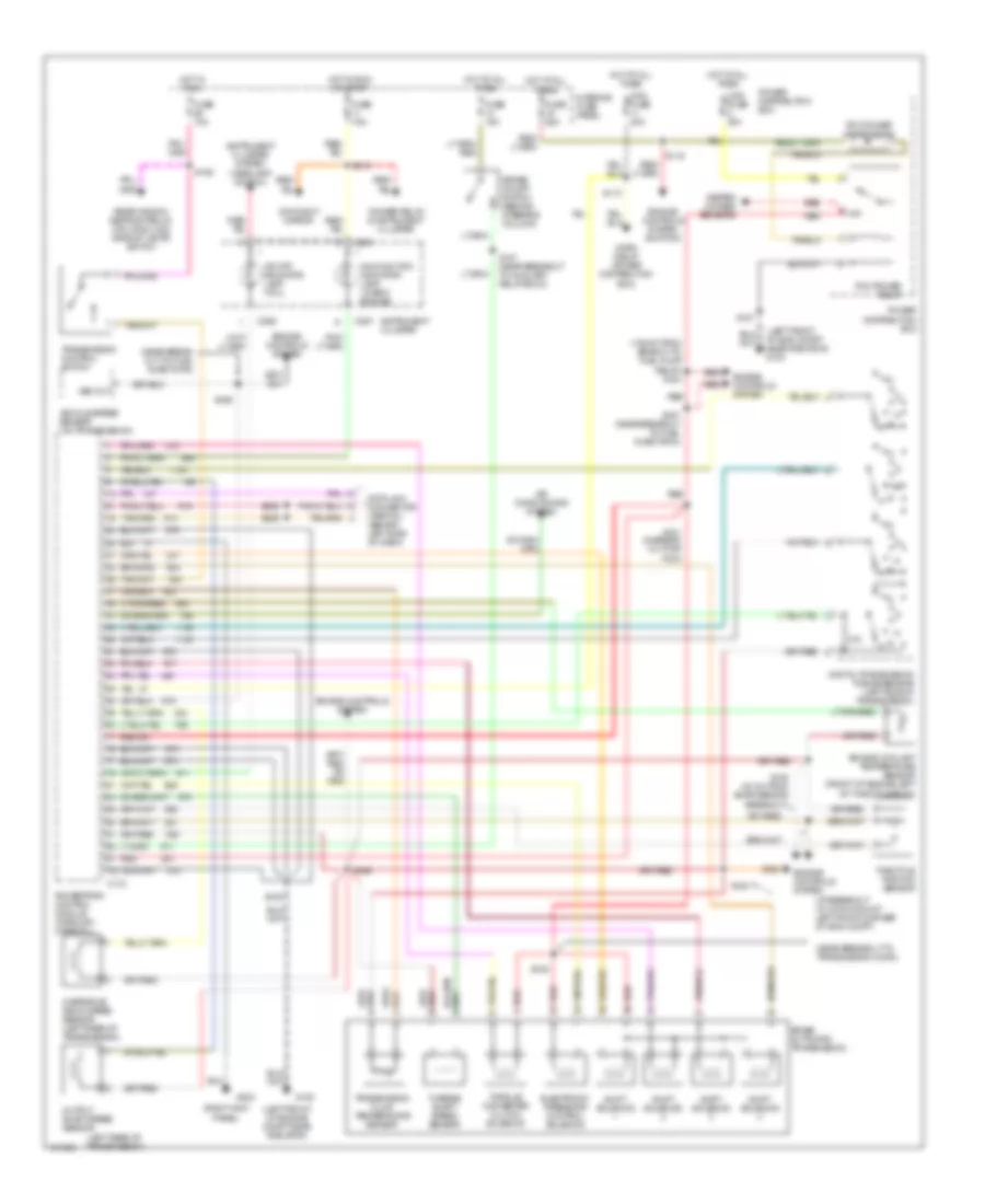
4.0L OHV, Transmission Wiring Diagram, 5R55E for Ford Explorer 1997
 https://portal-diagnostov.com/license.html
Automotive Electricians Portal FZCO
Automotive Electricians Portal FZCO
https://portal-diagnostov.com/license.html
https://portal-diagnostov.com/license.html
Automotive Electricians Portal FZCO
Automotive Electricians Portal FZCO
List of elements for 4.0L OHV, Transmission Wiring Diagram, 5R55E for Ford Explorer 1997:
- (135 mm from branch to fuel pump relay) s123
- (at breakout to 2-pin conn at left front corner of eng compt)
- (left front of eng compt near radiator) g100
- (left front of engine compt near radiator)
- (left rear of transmission)
- (near break- out to fuel injector 6)
- (near breakout to transmission conn)
- (right kick panel)
- 5r55e automatic transmission
- Air conditioning system
- Brake on/off switch (behind steering column)
- C172
- C286
- C287
- Data link connector (partial) (behind left side of dash)
- Day/night mirror
- Digital transmission range sensor (left side of transmission)
- Dimmer relay & instrument cluster
- Electronic pressure control solenoid
- Engine controls system
- Engine controls system (ignition)
- Engine coolant temperature sensor (front of engine left of throttle body)
- Fuse 10a
- Fuse 15a
- Fuse 25a
- Fuse 7.5a
- G100
- G203
- Heated oxygen sensors
- Horn relay (power distribution box)
- Hot at all times
- Hot in run
- Hot in run or start
- Instrument cluster
- Instrument cluster system (headlamp switch)
- Interior fuse panel
- Malfunction indicator lamp (check engine)
- Maxi fuse 20a
- Maxi fuse 30a
- O/d off indicator lamp (tcil)
- Output shaft speed sensor
- Overdrive drum speed sensor (left rear of transmission)
- Pcm power relay
- Pcm power relay diode
- Power distribution box
- Powertrain control module (through (firewall)
- R p
- Rear window defrost relay, drl module & backup lamps switch
- Red
- S101 (in break- out for pcm)
- S105
- S113
- S116
- S125
- S136 (40 cm from bmap sensor breakout)
- S137
- S147 (near breakout to auxiliary relay box 3)
- S162
- S166
- S167 (near breakout to fuel injector 6)
- S169
- S180
- S205
- S206
- S213
- Shift solenoid
- Throttle postion sensor
- Torque converter clutch solenoid
- Transmission control switch
- Transmission fluid temperature sensor
- Turbine shaft speed sensor
- Vehicle speed sensor (on transmission)
- Vss out
4.0L SOHC, Transmission Wiring Diagram, 5R55E for Ford Explorer 1997
List of elements for 4.0L SOHC, Transmission Wiring Diagram, 5R55E for Ford Explorer 1997:
- (135 mm from branch to fuel pump relay) s123
- (at breakout to 2-pin conn at left front corner of eng compt)
- (left front of eng compt near radiator) g100
- (left front of engine compt near radiator)
- (left rear of transmission)
- (near break- out to fuel injector 6)
- (near breakout to transmission conn)
- (right kick panel)
- 5r55e automatic transmission
- Air conditioning system
- Brake on/off switch (behind steering column)
- C172
- C286
- C287
- Data link connector (partial) (behind left side of dash)
- Day/night mirror
- Digital transmission range sensor (left side of transmission)
- Dimmer relay & instrument cluster
- Electronic pressure control solenoid
- Engine controls system
- Engine controls system (ignition)
- Engine coolant temperature sensor (front of engine left of throttle body)
- Fuse 10a
- Fuse 15a
- Fuse 25a
- Fuse 7.5a
- G100
- G203
- Heated oxygen sensors
- Horn relay (power distribution box)
- Hot at all times
- Hot in run
- Hot in run or start
- Instrument cluster
- Instrument cluster system (headlamp switch)
- Interior fuse panel
- Malfunction indicator lamp (check engine)
- Maxi fuse 20a
- Maxi fuse 30a
- O/d off indicator lamp (tcil)
- Output shaft speed sensor
- Overdrive drum speed sensor (left rear of transmission)
- Pcm power relay
- Pcm power relay diode
- Power distribution box
- Powertrain control module (through (firewall)
- R p
- Rear window defrost relay, drl module & backup lamps switch
- Red
- S101 (in break- out for pcm)
- S105
- S113
- S116
- S125
- S136 (40 cm from bmap sensor breakout)
- S137
- S147 (near breakout to auxiliary relay box 3)
- S162
- S166
- S167 (near breakout to fuel injector 6)
- S169
- S180
- S205
- S206
- S213
- Shift solenoid
- Throttle postion sensor
- Torque converter clutch solenoid
- Transmission control switch
- Transmission fluid temperature sensor
- Turbine shaft speed sensor
- Vehicle speed sensor (on transmission)
- Vss out
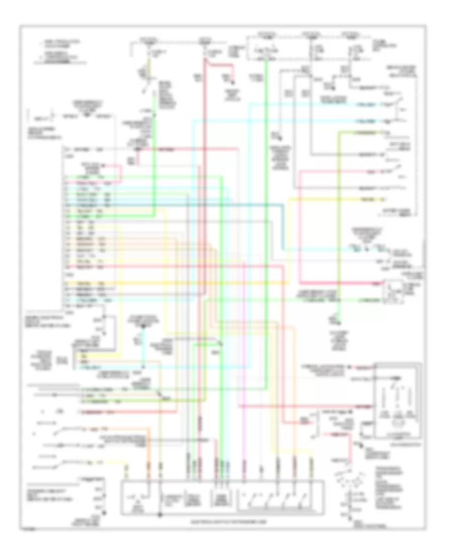
Electronic Transfer Case Wiring Diagram for Ford Explorer 1997
List of elements for Electronic Transfer Case Wiring Diagram for Ford Explorer 1997:
- (440 mm from electronic shift motor transfer case)
- (behind center of dash) relay module
- (in break out to gem) s250
- (left side of automatic transmission)
- (near break out to instrument cluster) s248
- (near break out to relay module)
- (near breakout for instrument cluster) s246
- (near breakout to instrument cluster) s247
- (near breakout to radio)
- (near electronic transfer case)
- (w/ dtr)
- (w/ tr)
- 1.1k ohms
- 3.9k ohms
- 4x4 high range ind
- 4x4 mode switch
- 87a
- A/t
- Accy delay relay
- Anti-lock brakes system
- Battery saver relay
- Brake on/off (boo) switch (behind steering column)
- C280
- C282
- C283
- C286
- Courtesy lamps (interior lights system)
- Digital transmission range sensor (dtr)
- Door locks & power seats
- Early production mountaineer
- Electronic shift motor transfer case
- Explorer & late production
- Front speed sensor
- Fuse 10a
- Fuse 13 15a
- Fuse 20a
- Fuse 28 7.5a
- G104 (rear of left front fender)
- G201 (under right side of dash)
- G203 (right kick panel)
- Generic electronic module (behind center of dash)
- H2l
- Headlamps, interior lamps & exterior lamps systems
- Hot at all times
- Hot in start
- Illumination lamp
- Instrument cluster
- Interior fuse panel
- Interior lights system (instrument illum- ination circuit)
- L2h
- M/t
- Magnetic clutch coil
- Maxi fuse 30a
- Memory seat module
- Mode
- Mountaineer
- Ohms
- Pnk
- Power distribution box
- Power tops & power windows systems
- Rear speed sensor
- S108
- S200
- S212 (near breakout to data link conn)
- S236
- S238
- S249
- S251
- S252
- S259
- Shift motor
- Solid state
- Torque on demand relay (right side of dash)
- Transfer case shift relay (behind center of dash)
- Transmission range sensor (tr)
- Vehicle speed sensor (on transmission)
- Vss out
5.0L
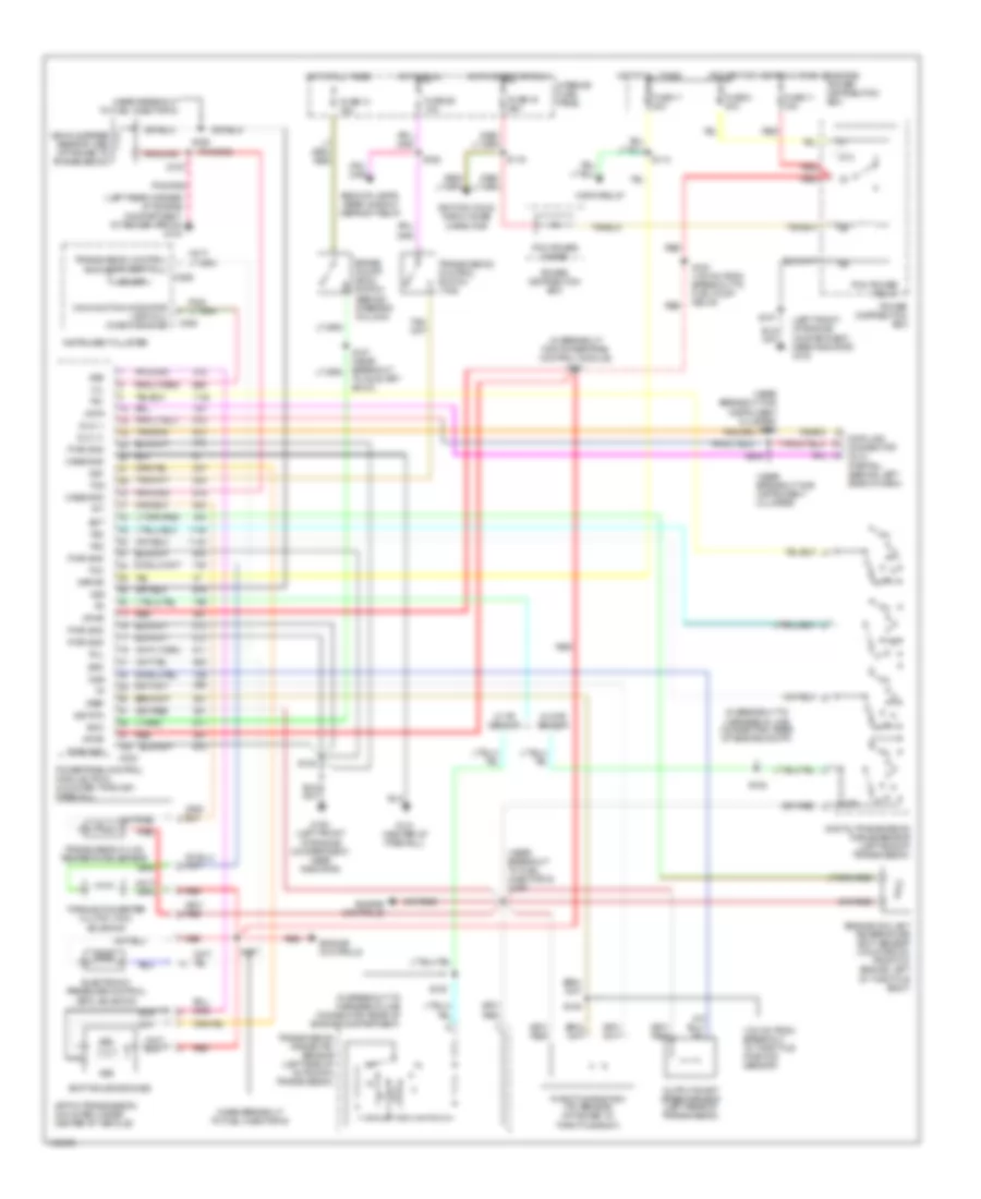
5.0L, Transmission Wiring Diagram, 4R70W for Ford Explorer 1997
List of elements for 5.0L, Transmission Wiring Diagram, 4R70W for Ford Explorer 1997:
- (100 mm from breakout to throttle position sensor)
- (in breakout for powertrain control module) s101
- (in breakout to harness in line connector, rear of engine compt)
- (in breakout to harness in-line connector, rear of engine compartment)
- (left front of engine compartment, near radiator) g100
- (left rear corner of engine compartment, at fender apron) g104
- (near breakout for instrument cluster)
- (near breakout for instrument cluster) s206
- (near breakout to fuel injector 6)
- (near breakout to fuel injector 6) s166
- (power for heated oxygen sensors)
- 4r70w transmission (mounted under center of vehicle)
- 87a
- Backup lamps, rear window defrost relay
- Boo
- Brake on/off (boo) switch (behind steering column)
- C202
- C286
- C288
- Case gnd
- Data
- Data link connector (dlc) (partial) (behind left side of dash)
- Digital transmission range sensor (left side of transmission)
- Dlc (+)
- Dlc (-)
- Ect
- Electronic pressure control (epc) solenoid
- Engine controls
- Engine coolant temperature (ect) sensor (mounted on front of engine, left of throttle body)
- Epc
- Fuse 11 15a
- Fuse 11 20a
- Fuse 13 15a
- Fuse 19 25a
- Fuse 2 30a
- Fuse 26 10a
- G100 (left front of engine compartment, near radiator)
- G121 (center of firewall)
- Horn relay
- Hot at all times
- Hot in run
- Hot in start or run
- Ignition coils, radio noise capacitor
- Instrument cluster
- Interior fuse panel
- Kapwr
- Malfunction indicator lamp (mil) (check engine)
- Mil
- N d
- Od off
- Oss
- Output shaft speed sensor (left rear of transmission)
- Pcm power diode
- Pcm power relay
- Power distribution box
- Powertrain control module (pcm) (mounted through firewall)
- Pwr gnd
- R p
- Red
- S105
- S113
- S116
- S123 (135 mm from breakout to fuel pump relay)
- S135
- S137
- S146
- S147 (near breakout to auxiliary box 3)
- S157
- S162
- S167
- S169
- S205
- Shift solenoids (ss)
- Sig rtn
- Ss1
- Ss2
- Tan/rg
- Tcc
- Tcil
- Tcs
- Tft
- Throttle position (tp) sensor (attached to throttle body)
- Torque converter clutch (tcc) solenoid
- Tr1
- Tr2
- Tr3
- Transmission control indicator lamp (tcil)
- Transmission control switch (tcs)
- Transmission fluid temperature sensor
- Transmission range (tr) sensor (left side of automatic transmission)
- Vehicle speed sensor (vss) (attached to transmission)
- Vpwr
- Vref
- Vss
- W/ dtr sensor
- W/ tr sensor
Electronic Transfer Case Wiring Diagram for Ford Explorer 1997
List of elements for Electronic Transfer Case Wiring Diagram for Ford Explorer 1997:
- (440 mm from electronic shift motor transfer case)
- (behind center of dash) relay module
- (in break out to gem) s250
- (left side of automatic transmission)
- (near break out to instrument cluster) s248
- (near break out to relay module)
- (near breakout for instrument cluster) s246
- (near breakout to instrument cluster) s247
- (near breakout to radio)
- (near electronic transfer case)
- (w/ dtr)
- (w/ tr)
- 1.1k ohms
- 3.9k ohms
- 4x4 high range ind
- 4x4 mode switch
- 87a
- A/t
- Accy delay relay
- Anti-lock brakes system
- Battery saver relay
- Brake on/off (boo) switch (behind steering column)
- C280
- C282
- C283
- C286
- Courtesy lamps (interior lights system)
- Digital transmission range sensor (dtr)
- Door locks & power seats
- Early production mountaineer
- Electronic shift motor transfer case
- Explorer & late production
- Front speed sensor
- Fuse 10a
- Fuse 13 15a
- Fuse 20a
- Fuse 28 7.5a
- G104 (rear of left front fender)
- G201 (under right side of dash)
- G203 (right kick panel)
- Generic electronic module (behind center of dash)
- H2l
- Headlamps, interior lamps & exterior lamps systems
- Hot at all times
- Hot in start
- Illumination lamp
- Instrument cluster
- Interior fuse panel
- Interior lights system (instrument illum- ination circuit)
- L2h
- M/t
- Magnetic clutch coil
- Maxi fuse 30a
- Memory seat module
- Mode
- Mountaineer
- Ohms
- Pnk
- Power distribution box
- Power tops & power windows systems
- Rear speed sensor
- S108
- S200
- S212 (near breakout to data link conn)
- S236
- S238
- S249
- S251
- S252
- S259
- Shift motor
- Solid state
- Torque on demand relay (right side of dash)
- Transfer case shift relay (behind center of dash)
- Transmission range sensor (tr)
- Vehicle speed sensor (on transmission)
- Vss out

 Čeština
 Dansk
Dansk Deutsch
 Ελληνικά
 English
 Español
 Suomi
Suomi Français
 Français
 עברית
עברית Hrvatski
 Magyar
 Italiano
 日本語
日本語 한국어
한국어 Nederlands
 Polski
 Português
 Português
 Română
 Русский
 Slovenčina
 Slovenščina
 Svenska
 Türkçe
 中文 (中国)