TRANSMISSION
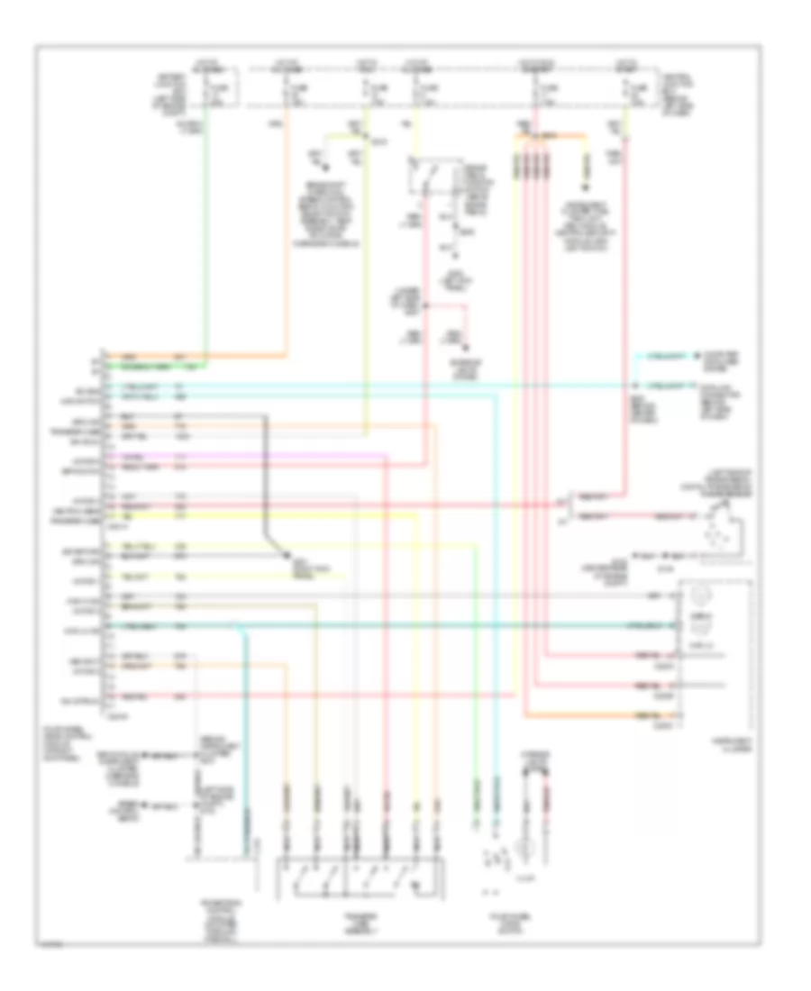
4WD Wiring Diagram, Early Production for Ford Explorer Sport Trac 2001
 https://portal-diagnostov.com/license.html
Automotive Electricians Portal FZCO
Automotive Electricians Portal FZCO
https://portal-diagnostov.com/license.html
https://portal-diagnostov.com/license.html
Automotive Electricians Portal FZCO
Automotive Electricians Portal FZCO
List of elements for 4WD Wiring Diagram, Early Production for Ford Explorer Sport Trac 2001:
- (behind instrument cluster) s213
- (left side of transmission) digital transmission range sensor
- (under left side of dash) s227
- 4wd hi
- 4wd hi ind
- 4wd lo
- 4wd lo ind
- 4wd switch
- Battery junction box (left side of engine compt)
- Bpp switch
- Brake pedal position switch (above brake pedal)
- Brake shift interlock, speed control servo, function select switch assembly, temp blend door actuator, gem module, overhead console
- C175
- C220a
- C220b
- C220c
- C281a
- C281b
- Central junction box (behind left side of dash)
- Computer data lines system
- Data link connector (behind left side of dash)
- Exterior lights system
- Four-wheel drive control module (at right kick panel)
- Four-wheel drive switch
- Fuse 15a
- Fuse 20a
- Fuse 7.5a
- G100 (center rear of engine compt)
- G200 (right kick panel)
- G201 (right kick panel)
- Ground
- Hot at all times
- Hot in run
- Hot in run or start
- Ign (run)
- Ign (st/run)
- Illum
- Instrument cluster
- Interior lights system
- Iso bus
- Main light switch, belt minder module
- Motor 1
- Motor 2
- Motor 3
- Motor 4
- Motor 5
- Nca
- Neutral sens
- Off
- Overhead console, instrument cluster, gem module
- Powertrain control module (mounted through firewall)
- S145
- S206
- S208 (behind center of dash)
- S216
- S218
- Sig return
- Speed control servo
- Transfer case
- Transfer case assembly
- Vss input
4WD Wiring Diagram, Late Production for Ford Explorer Sport Trac 2001
List of elements for 4WD Wiring Diagram, Late Production for Ford Explorer Sport Trac 2001:
- (behind instrument cluster) s213
- (left side of transmission) digital transmission range sensor
- (under left side of dash) s227
- 4wd hi
- 4wd hi ind
- 4wd lo
- 4wd lo ind
- 4wd switch
- A/t
- Battery junction box (left side of engine compt)
- Bpp switch
- Brake pedal position switch (above brake pedal)
- Brake shift interlock, speed control servo, function select switch assembly, temp blend door actuator, overhead console
- C175
- C220a
- C220b
- C220c
- C281a
- C281b
- Central junction box (behind left side of dash)
- Computer data lines system
- Data link connector (behind left side of dash)
- Exterior lights system
- Four-wheel drive control module (at right kick panel)
- Four-wheel drive switch
- Fuse 15a
- Fuse 20a
- Fuse 7.5a
- G100 (center rear of engine compt)
- G201 (right kick panel)
- G300 (left kick panel)
- Gem module, instrument cluster, overhead console
- Ground
- Hot at all times
- Hot in run
- Hot in run or start
- Hot in start
- Ign (run)
- Ign (st/run)
- Illum
- Instrument cluster
- Instrument cluster, fuel tank unit, gem module, central security module, main light switch
- Interior lights system
- Iso bus
- M/t
- Motor 1
- Motor 2
- Motor 3
- Motor 4
- Motor 5
- Nca
- Neutral sens
- Off
- Powertrain control module (mounted through firewall)
- S145
- S206
- S208 (behind center of dash)
- S216
- S218
- Sig return
- Speed control servo
- Transfer case
- Transfer case assembly
- Vss input
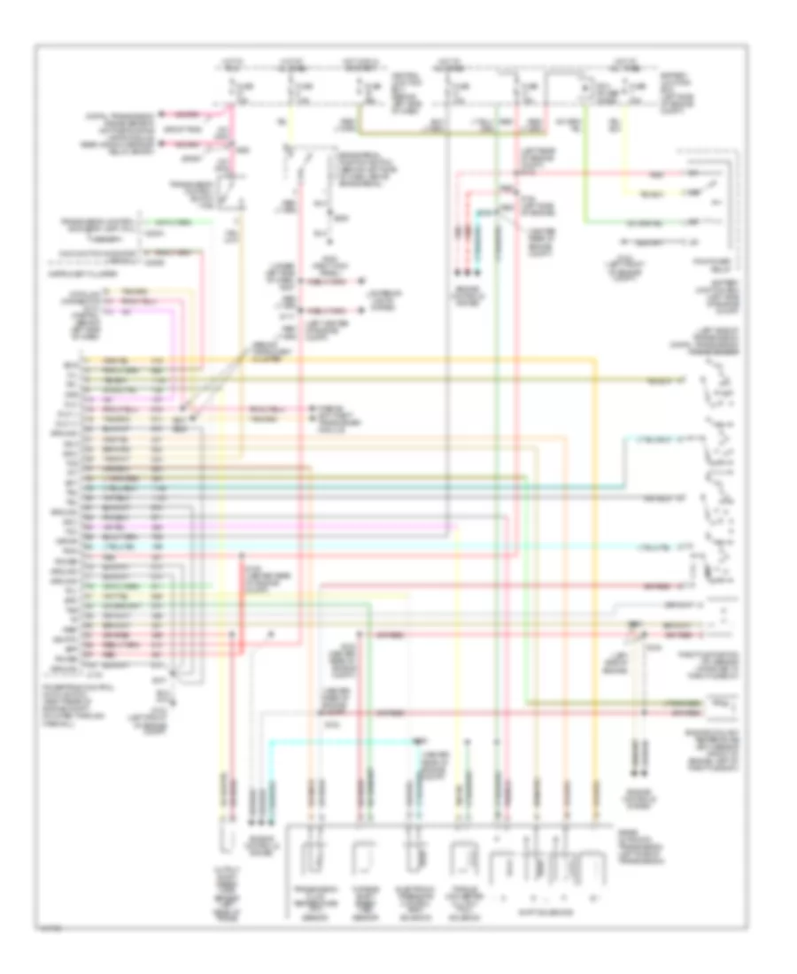
A/T Wiring Diagram, Early Production for Ford Explorer Sport Trac 2001
List of elements for A/T Wiring Diagram, Early Production for Ford Explorer Sport Trac 2001:
- (behind instrument cluster
- (center rear of engine compt)
- (dlc) (partial) (behind left side of dash)
- (left center of engine compt)
- (left rear of engine compt) s113
- (left side of engine)
- (left side of transmission) digital transmission range sensor
- (under left side of dash) s227
- 5r55e automatic transmission (left side of transmission)
- Battery junction box (left side of engine compt)
- Bpp
- Brake pedal position switch (behind left side of dash, above brake pedal)
- C175
- C220a
- C220b
- Central junction box (behind left side of dash)
- Data link connector
- Digital transmission range sensor, daytime running lamps module, rear window defrost relay (sport)
- Dlc
- Dlc (+)
- Dlc (-)
- Ect
- Electronic pressure control (epc) solenoid
- Engine controls system
- Engine coolant temperature (ect) sensor (front of engine, left of throttle body)
- Epc
- Exterior lights system
- Fuse 10a
- Fuse 15a
- Fuse 25a
- Fuse 30a
- Fuse 7.5a
- G103 (left front of engine compt)
- G104 (left front of engine compt)
- G200 (right kick panel)
- Ground
- Hot at all times
- Hot in run
- Hot in run or start
- Instrument cluster
- Kapwr
- Malfunction indicator lamp (mil)
- Mil
- O/d off
- Of engine)
- Oss
- Output shaft speed (oss) sensor (left rear of trans)
- Passive anti-theft transceiver module
- Pcm power diode
- Pcm power relay
- Power
- Powertrain control module (pcm) (right rear of engine compt, mounted through firewall)
- R p
- Red
- S100
- S102
- S103
- S104 (left side red
- S106
- S107
- S108 (center rear of engine compt)
- S117
- S129 (center rear of engine compt)
- S132
- S206
- S220
- S221
- S223
- Shift solenoids
- Sig rtn
- Sport
- Sport trac
- Ss a
- Ss b
- Ss c
- Ss d
- Tcc
- Tcil
- Tcs
- Tft
- Throttle position (tp) sensor (attached to throttle body)
- Torque converter clutch (tcc) solenoid
- Tr1
- Tr2
- Tr3a
- Tr4
- Transmission control indicator lamp (tcil)
- Transmission control switch (tcs)
- Transmission fluid temperature (tft) sensor
- Tss
- Turbine shaft speed (tss) sensor
- Vref
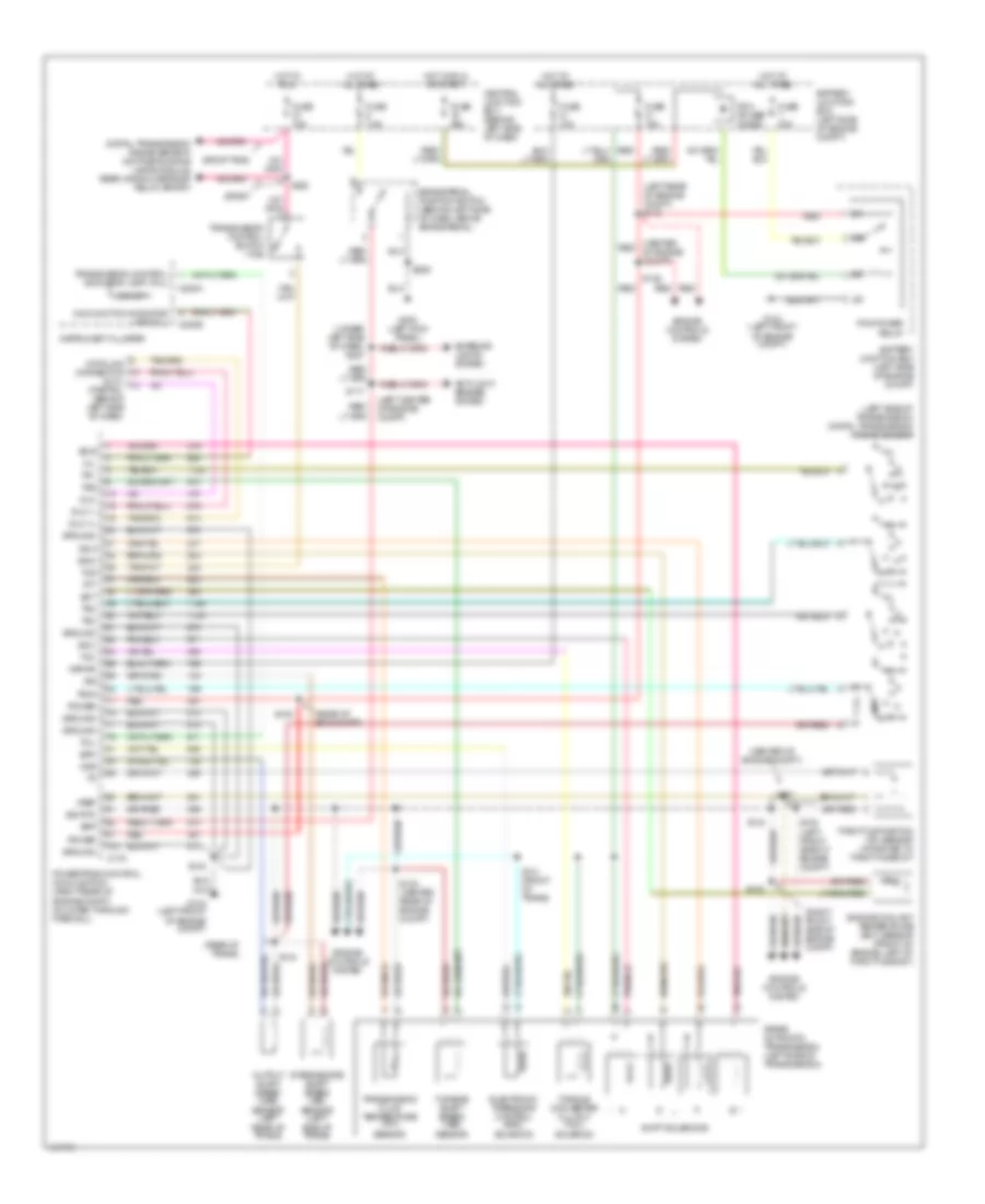
A/T Wiring Diagram, Late Production for Ford Explorer Sport Trac 2001
List of elements for A/T Wiring Diagram, Late Production for Ford Explorer Sport Trac 2001:
- (center of engine compt)
- (center red of engine compt)
- (dlc) (partial) (behind left side of dash)
- (left center of engine compt)
- (left rear of engine compt) s113
- (left side of transmission) digital transmission range sensor
- (rear of eng compt)
- (rear of trans)
- (right front side of engine compt)
- (under left side of dash) s227
- 5r55e automatic transmission (left side of transmission)
- Anti-lock brakes system
- Battery junction box (left side of engine compt)
- Bpp
- Brake pedal position switch (behind left side of dash, above brake pedal)
- C175
- C220a
- C220b
- Central junction box (behind left side of dash)
- Data link connector
- Digital transmission range sensor, daytime running lamps module, rear window defrost relay (sport)
- Dlc
- Dlc (+)
- Dlc (-)
- Ect
- Electronic pressure control (epc) solenoid
- Engine controls system
- Engine coolant temperature (ect) sensor (front of engine, left of throttle body)
- Epc
- Exterior lights system
- Fuse 10a
- Fuse 15a
- Fuse 25a
- Fuse 30a
- Fuse 7.5a
- G103 (left front of engine compt)
- G104 (left front of engine compt)
- G300 (left kick panel)
- Ground
- Hot at all times
- Hot in run
- Hot in run or start
- Instrument cluster
- Intermediate shaft speed (iss) sensor (left side of trans)
- Iss
- Kapwr
- Malfunction indicator lamp (mil)
- Mil
- O/d off
- Oss
- Output shaft speed (oss) sensor (left rear of trans)
- Pcm power diode
- Pcm power relay
- Power
- Powertrain control module (pcm) (right rear of engine compt, mounted through firewall)
- R p
- Red
- S117
- S133
- S135 (left front side of engine compt)
- S136
- S137
- S140 (center rear of engine compt)
- S141 (front of trans)
- S142
- S143
- S144
- S145
- S206
- S223
- Shift solenoids
- Sig rtn
- Sport
- Sport trac
- Ss a
- Ss b
- Ss c
- Ss d
- Tcc
- Tcil
- Tcs
- Tft
- Throttle position (tp) sensor (attached to throttle body)
- Torque converter clutch (tcc) solenoid
- Tr1
- Tr2
- Tr3a
- Tr4
- Transmission control indicator lamp (tcil)
- Transmission control switch (tcs)
- Transmission fluid temperature (tft) sensor
- Tss
- Turbine shaft speed (tss) sensor
- Vref

 Čeština
 Dansk
Dansk Deutsch
 Ελληνικά
 English
 Español
 Suomi
Suomi Français
 Français
 עברית
עברית Hrvatski
 Magyar
 Italiano
 日本語
日本語 한국어
한국어 Nederlands
 Polski
 Português
 Português
 Română
 Русский
 Slovenčina
 Slovenščina
 Svenska
 Türkçe
 中文 (中国)