TRANSMISSION
3.8L
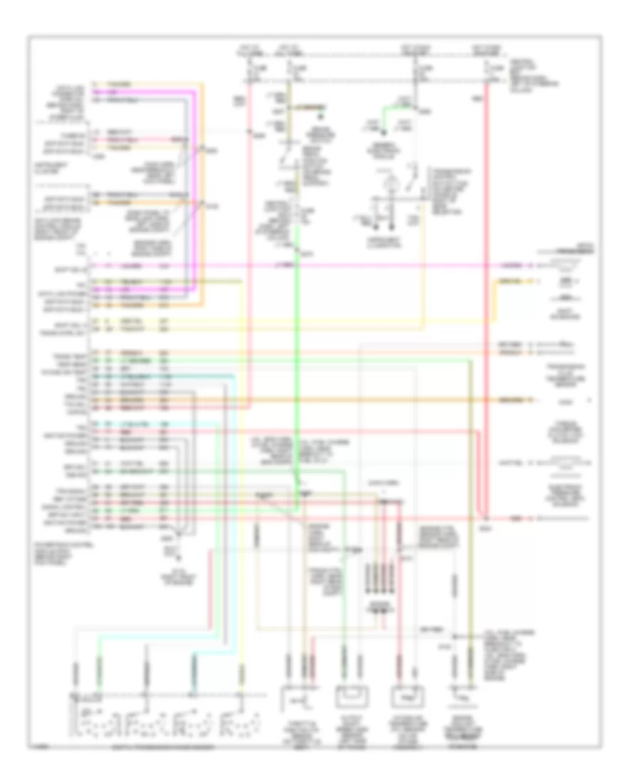
3.8L, A/T Wiring Diagram for Ford Mustang 2000
 https://portal-diagnostov.com/license.html
Automotive Electricians Portal FZCO
Automotive Electricians Portal FZCO
https://portal-diagnostov.com/license.html
https://portal-diagnostov.com/license.html
Automotive Electricians Portal FZCO
Automotive Electricians Portal FZCO
List of elements for 3.8L, A/T Wiring Diagram for Ford Mustang 2000:
- (dash panel to headlamp harn, left side of engine compt)
- (engine ctrl sensor harn, right rear of engine compt)
- (engine harn, right rear of eng compt)
- (engine harn, right side of engine compt)
- (main harn)
- (main harn, near breakout near left kick panel)
- (trans ctrl harn, near right rear of eng compt)
- 3.8l
- 3.8l: (fuel charge harn, near breakout to injector 2) 4.6l: (eng harn, & fuel charge harn, right side of engine)
- 3.8l: (fuel charge harn, near brekout to fuel inj 2)
- 4.6l
- 4.6l: (eng harn, & fuel charge harn, right rear of eng compt)
- 4r70w transmission
- Anti-lock brake control module (right front of engine compt)
- Bpp sw input
- Brake pedal position switch (on brake pedal support)
- Brake pressure switch
- C250
- Central junction box (behind dash, left of steering column)
- Data link connector (partial) (behind dash, right of steer clmn)
- Data link power
- Digital transmission range sensor
- Electronic pressure control (epc) solenoid
- Engine controls
- Engine coolant temperature (ect) sensor (top front
- Epc sol
- Fuse 15a
- Fuse 20a
- Fuse 5a
- Fused b+
- G119 (right front of engine)
- Generic electronic module
- Ground
- Hot at all times
- Hot in run or start
- Ignition power
- Instrument cluster
- Instrument illumination
- Intake air temp
- Intake air temperature (iat) sensor (on air intake assembly)
- Kapwr
- Of engine)
- Oss sig
- Output shaft speed (oss) sensor (left side of trans)
- Powertrain control module (pcm) (behind right kick panel)
- Red
- Ref votage
- S121
- S126
- S129
- S130
- S134
- S135
- S200
- S207
- S224 (4.6l)
- S234
- S250
- S252
- S253
- S259
- S262
- S275
- Scp data bus +
- Scp data bus -
- Shift sol a
- Shift sol b
- Shift solenoids
- Signal control
- Ssa
- Ssb
- Tcc sol
- Temp sens
- Throttle position (tp) sensor (on throttle body)
- Torque converter clutch (tcc) solenoid
- Tps signal
- Tr1
- Tr2
- Tr3
- Tr4
- Trans cntrl sw
- Trans temp
- Transmission control switch (tcs) (on center console, right of gear selector)
- Transmission fluid temperature sensor
4.6L
4.6L SOHC, A/T Wiring Diagram for Ford Mustang 2000
List of elements for 4.6L SOHC, A/T Wiring Diagram for Ford Mustang 2000:
- (dash panel to headlamp harn, left side of engine compt)
- (engine ctrl sensor harn, right rear of engine compt)
- (engine harn, right rear of eng compt)
- (engine harn, right side of engine compt)
- (main harn)
- (main harn, near breakout near left kick panel)
- (trans ctrl harn, near right rear of eng compt)
- 3.8l
- 3.8l: (fuel charge harn, near breakout to injector 2) 4.6l: (eng harn, & fuel charge harn, right side of engine)
- 3.8l: (fuel charge harn, near brekout to fuel inj 2)
- 4.6l
- 4.6l: (eng harn, & fuel charge harn, right rear of eng compt)
- 4r70w transmission
- Anti-lock brake control module (right front of engine compt)
- Bpp sw input
- Brake pedal position switch (on brake pedal support)
- Brake pressure switch
- C250
- Central junction box (behind dash, left of steering column)
- Data link connector (partial) (behind dash, right of steer clmn)
- Data link power
- Digital transmission range sensor
- Electronic pressure control (epc) solenoid
- Engine controls
- Engine coolant temperature (ect) sensor (top front
- Epc sol
- Fuse 15a
- Fuse 20a
- Fuse 5a
- Fused b+
- G119 (right front of engine)
- Generic electronic module
- Ground
- Hot at all times
- Hot in run or start
- Ignition power
- Instrument cluster
- Instrument illumination
- Intake air temp
- Intake air temperature (iat) sensor (on air intake assembly)
- Kapwr
- Of engine)
- Oss sig
- Output shaft speed (oss) sensor (left side of trans)
- Powertrain control module (pcm) (behind right kick panel)
- Red
- Ref votage
- S121
- S126
- S129
- S130
- S134
- S135
- S200
- S207
- S224 (4.6l)
- S234
- S250
- S252
- S253
- S259
- S262
- S275
- Scp data bus +
- Scp data bus -
- Shift sol a
- Shift sol b
- Shift solenoids
- Signal control
- Ssa
- Ssb
- Tcc sol
- Temp sens
- Throttle position (tp) sensor (on throttle body)
- Torque converter clutch (tcc) solenoid
- Tps signal
- Tr1
- Tr2
- Tr3
- Tr4
- Trans cntrl sw
- Trans temp
- Transmission control switch (tcs) (on center console, right of gear selector)
- Transmission fluid temperature sensor

 Čeština
 Dansk
Dansk Deutsch
 Ελληνικά
 English
 Español
 Suomi
Suomi Français
 Français
 עברית
עברית Hrvatski
 Magyar
 Italiano
 日本語
日本語 한국어
한국어 Nederlands
 Polski
 Português
 Português
 Română
 Русский
 Slovenčina
 Slovenščina
 Svenska
 Türkçe
 中文 (中国)