TRANSMISSION
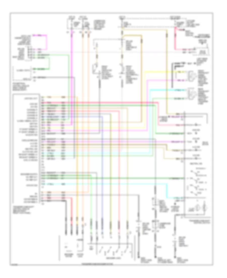
A/T Wiring Diagram for GMC Sonoma 2004
 https://portal-diagnostov.com/license.html
Automotive Electricians Portal FZCO
Automotive Electricians Portal FZCO
https://portal-diagnostov.com/license.html
https://portal-diagnostov.com/license.html
Automotive Electricians Portal FZCO
Automotive Electricians Portal FZCO
List of elements for A/T Wiring Diagram for GMC Sonoma 2004:
- (rear of right cyl head) g103
- (under dash, on heater case) body control module
- +5v
- 1-2 shift solenoid
- 1-2 ss
- 2-3 shift solenoid
- 2-3 ss
- 2wd
- 3-2 shift solenoid
- 3-2 ss
- 4wd
- 4wd low
- A/t fluid pressure manual valve position switch
- A/t shift lock solenoid
- A10
- A11
- A12
- Abs fuse 22 10a
- Automatic transmission
- B c2
- B8 c2
- Bare
- Blower motor resistor)
- Brk sw
- C116a (4wd)
- Cls 2 data
- Clstr fuse 11 10a
- Cruise control & anti-lock brakes systems
- D3, d2
- D4, d2
- Data link connector (under left side of dash)
- Ecm b fuse 20a
- Ecm i fuse 15a
- Ect sig
- Electronic brake control module
- Engine coolant temperature sensor (on left cylinder head, between rear plugs)
- Fluid temp sensor
- Frt axle sw
- G104 (rear of left cyl head)
- G104 rear of left cyl head)
- G105 (rear of left cyl head)
- G117 (left rear of eng compt)
- Gauges fuse 4 10a
- Gnd
- Hot at all times
- Hot in off, run, or start
- Hot in run
- Hot in run or start
- I/p fuse block (on left end of dash)
- Ign
- Instrument cluster
- Instrument panel cluster (ipc)
- Lo ref
- Mil (service engine soon ind)
- Mil ctrl
- Nca
- Park/neutral position switch (left side of transmission)
- Pc sol hi
- Pc sol lo
- Pnk
- Powertrain control module (right side of engine compt)
- Press ctrl solenoid
- Prnd a
- Prnd b
- Prnd c
- Prnd p
- Range b
- Range c
- Red
- Red a
- Red b
- Rev, lo
- S106
- S113
- S116
- S134
- S140
- S152
- S203
- Sens gnd
- Solid state
- Splice pack sp201 (near body relay block)
- Stoplamp switch (on brake pedal support bracket)
- Tan
- Tcc pwm
- Tcc pwm solenoid
- Tcc sol
- Tcc solenoid
- Tft sens sig
- Throttle position sensor (on throttle body assembly)
- Tp sig
- Trans rng a
- Transfer case circuit
- Underhood fuse block (on top of left front fender)
- Utility w/ floor shift
- Vehicle speed sensor (right rear of trans)
- Vss hi
- Vss lo
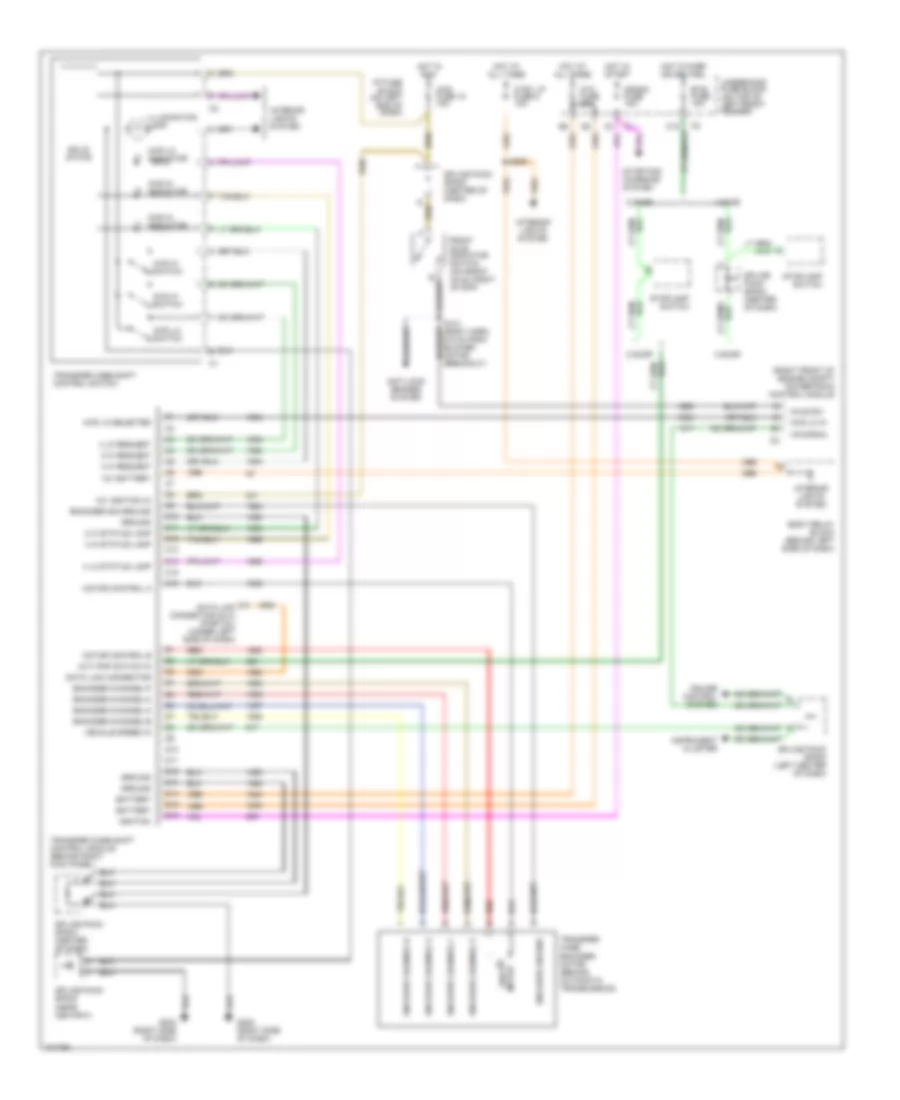
Transfer Case Wiring Diagram, with 2-Speed Automatic Transfer Case for GMC Sonoma 2004
List of elements for Transfer Case Wiring Diagram, with 2-Speed Automatic Transfer Case for GMC Sonoma 2004:
- (left rear of engine compt) g117
- +8v ref
- +8v ref out
- 2-hi ind
- 4-hi ind
- 4-lo ind
- 4wd fuse 15 10a
- 4wd ind
- 4wd lo
- 4wd lo ind sig
- 4wd sw sig
- Atc fuse 20a
- Axle sw sig
- Bare
- Body control module
- Body relay block (behind left side of dash)
- C1 e5
- Channel-a
- Channel-b
- Channel-c
- Channel-p
- Class ii data
- Class ii serial data
- Clutch sol sig
- Crank fuse 10a
- Data link connector (dlc) (partial) (under left side of dash)
- Decoder logic
- E10
- E11
- E12
- E13
- E14
- E15
- E16
- Encoder motor
- Encoder sig rtn
- F10
- F11
- F12
- F13
- F14
- F15
- F16
- Front axle indicator switch (on front axle, right of diff)
- Front axle vacuum solenoid (on firewall, near windshield wiper motor)
- Front propshaft speed sensor (top left rear of transfer case
- Ft shaft speed hi
- Ft shaft speed lo
- Fwd
- G105 (rear of left cylinder head)
- G203 (right side of dash)
- G205 (right side of dash)
- Gauges fuse 4 10a
- Gnd
- Ground
- Hot at all times
- Hot in run
- Hot in run or start
- Hot in start
- I/p fuse block (on left end of dash)
- Ignition
- Illum lamps
- Instrument panel cluster
- Interior lights system
- Lock sol out
- Module ground
- Motor feed a
- Motor feed b
- Motor lock
- Nca
- Neutral ind
- Pnk
- Powertrain control module (right side of engine compt)
- Pwr
- Rear propshaft speed sensor (top right rear of transfer case
- Red
- Rr shaft speed hi
- Rr shaft speed lo
- S134 bare
- S152
- Service 4wd ind
- Solid state
- Splice pack sp200 (center of dash)
- Splice pack sp201 (near body relay block)
- Splice pack sp203 (near ashtray)
- Splice pack sp204 (center of dash)
- Tan
- Transfer case encoder motor
- Transfer case shift control module (behind right front kick panel)
- Transfer case shift control switch
- Underhood fuse block
- Underhood fuse block (on top of left front fender)
Transfer Case Wiring Diagram, with 2-Speed Selectable Transfer Case for GMC Sonoma 2004
List of elements for Transfer Case Wiring Diagram, with 2-Speed Selectable Transfer Case for GMC Sonoma 2004:
- (a/t) pnp switch in
- (right front of engine compt) powertrain control module
- 12v battery
- 12v ignition (3)
- 2 door
- 2 hi request
- 2 hi status lamp
- 2wd hi indicator
- 2wd hi switch
- 4 door
- 4 hi request
- 4 hi status lamp
- 4 lo request
- 4 lo status lamp
- 4wd fuse 15 10a
- 4wd hi indicator
- 4wd hi switch
- 4wd lo in
- 4wd lo indicator
- 4wd lo selected
- 4wd lo switch
- Anti-lock brakes system
- Atc fuse 20a
- Axle sw
- Battery
- Body relay block (behind left side of dash)
- Btsi fuse 10a
- C10
- C11
- C12
- C13
- C14
- C15
- C16
- Crank fuse 10a
- Cruise control system
- Ctsy lp fuse 8 10a
- D10
- D11
- D12
- D13
- D14
- D15
- D16
- Data link connector
- Data link connector (dlc) (partial) (under left side of dash)
- Encoder channel a
- Encoder channel b
- Encoder channel c
- Encoder channel p
- Encoder channel-a
- Encoder channel-b
- Encoder channel-c
- Encoder channel-p
- Encoder ground
- Encoder sig ground
- Front axle indicator switch (on front axle, right of diff)
- G203 (right side of dash)
- G205 (right side of dash)
- Ground
- Hot at all times
- Hot in park or neutral
- Hot in run
- Hot in start
- I/p fuse block (on left end of dash)
- Ignition
- Illumination lamp
- Instrument cluster
- Interior lights system
- M shift motor
- Motor control a
- Motor control b
- Red
- S121 (body harn, 6.5 cm from blower motor breakout)
- S208
- Solid state
- Splice pack sp204 (center of dash)
- Splice pack sp200 (center of dash)
- Splice pack sp200 (left center of dash)
- Splice pack sp203 (near ashtray)
- Splice pack sp204 (center of dash)
- Starting/ charging system
- Stoplamp switch
- Transfer case encoder motor (behind automatic transmission)
- Transfer case shift control module (behind right kick panel)
- Transfer case shift control switch
- Underhood fuse block (on top of left front fender)
- Vehicle speed in
- Vs signal

 Čeština
 Dansk
Dansk Deutsch
 Ελληνικά
 English
 Español
 Suomi
Suomi Français
 Français
 עברית
עברית Hrvatski
 Magyar
 Italiano
 日本語
日本語 한국어
한국어 Nederlands
 Polski
 Português
 Português
 Română
 Русский
 Slovenčina
 Slovenščina
 Svenska
 Türkçe
 中文 (中国)