AUTOMOTIVE ELECTRICIANS PORTAL

TRANSMISSION – Honda Odyssey EX 2014 – SYSTEM WIRING DIAGRAMS

TRANSMISSION

Transmission Wiring Diagram (1 of 2) for Honda Odyssey EX 2014

Transmission Wiring Diagram (1 of 2) for Honda Odyssey EX 2014 https://portal-diagnostov.com/license.html
https://portal-diagnostov.com/license.html Automotive Electricians Portal FZCO Automotive Electricians Portal FZCO
Download PDF file

List of elements for Transmission Wiring Diagram (1 of 2) for Honda Odyssey EX 2014:

  • (behind instrument cluster) driver's junction box 1
  • 6th clutch transmission fluid pressure switch e (top of transaxle)
  • A16
  • A17
  • A18
  • A19
  • A24
  • A25
  • A26
  • A27
  • A32
  • A48
  • A49
  • Apsa
  • Apsb
  • Atpd
  • Atpfwd
  • Atpl
  • Atpn
  • Atpp
  • Atpr
  • Atprvs
  • B10
  • B21
  • B34
  • B35
  • B36
  • B37
  • B38
  • B42
  • B43
  • B44
  • Bksw
  • Bkswnc
  • C101
  • C12
  • C14
  • C15
  • C16
  • C17
  • C18
  • C19
  • C20
  • C205
  • C21
  • C210
  • C212
  • C25
  • C26
  • C27
  • C28
  • C31
  • C33
  • C35
  • C37
  • C38
  • C46
  • Computer data lines system
  • D4sw
  • Driver's junction box 1 (behind instrument cluster)
  • Driver's under-dash fuse/relay relay (left end of dash)
  • Engine controls system
  • F-can-h
  • F-can-l
  • F10
  • F21
  • Fuse 10 15a
  • Fuse 10a
  • Fuse 15a
  • Fuse 20a
  • Fuse 7.5a
  • G101 (right rear of engine compt)
  • Hot at all times
  • Hot in on or start
  • Ig1
  • Ignition coil relay
  • Igp
  • J/c c102 (top right side of engine)
  • J/c c104 (top right side of engine)
  • J/c c105 (top right side of engine)
  • Line pressure solenoid valve a (left side of transaxle)
  • Lsa
  • Lsb
  • Lsc
  • Lsd
  • Map
  • Map sensor (right rear of engine)
  • Memory systems
  • Mrly
  • Op2sw
  • Op3sw
  • Op4sw
  • Op5sw
  • Op6sw
  • Output shaft (countershaft) speed sensor (bottom of transaxle)
  • Pcm (right side of engine compt)
  • Pg2
  • Pgm-fi main relay 1
  • Pla
  • Pnk
  • R p
  • Red
  • Scs
  • Sg1
  • Sg2
  • Sg3
  • Sg4
  • Sg6
  • Sha
  • Shb
  • Shc
  • Shift control solenoid valve a (side of transaxle)
  • Shift control solenoid valve b (side of transaxle)
  • Shift control solenoid valve c (side of transaxle)
  • Shift interlock system
  • Starting/ charging system
  • Tan
  • Tatf
  • Transmission range switch (top of transaxle)
  • Under-hood fuse/relay box (right rear of engine compt)
  • Vbsol
  • Vbsol2
  • Vcc1
  • Vcc2
  • Vcc3
  • Vcc4
  • W/ memory

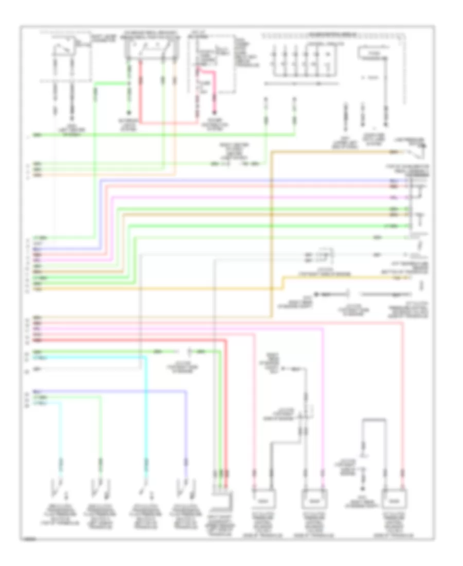
Transmission Wiring Diagram (2 of 2) for Honda Odyssey EX 2014

Transmission Wiring Diagram (2 of 2) for Honda Odyssey EX 2014 https://portal-diagnostov.com/license.html
https://portal-diagnostov.com/license.html Automotive Electricians Portal FZCO Automotive Electricians Portal FZCO
Get access to all wiring diagrams of the carDownload PDF file

List of elements for Transmission Wiring Diagram (2 of 2) for Honda Odyssey EX 2014:

  • (on brake pedal bracket) brake pedal position switch
  • (right center of dash) center junction box
  • (right rear of engine compt) g101
  • (top of accelerator pedal assembly) app sensor
  • 2nd clutch transmission fluid pressure switch a (left side of transaxle)
  • 3rd clutch transmission fluid pressure switch b (top of transaxle)
  • 4th clutch transmission fluid pressure switch c (bottom of transaxle)
  • 5th clutch transmission fluid pressure switch d (bottom of transaxle)
  • A/t clutch pressure control solenoid valve a (side of transaxle)
  • A/t clutch pressure control solenoid valve b (side of transaxle)
  • A/t clutch pressure control solenoid valve c (side of transaxle)
  • A/t clutch pressure control solenoid valve d (side of transaxle)
  • Atf temperature sensor (bottom of transaxle)
  • Computer data lines system
  • Control circuits
  • D4 switch
  • Exterior lights system
  • F-can
  • Fuse 20a
  • G101 (right rear of engine compt)
  • G401 (upper left end of dash)
  • G403 (left center of dash)
  • Gauge control module
  • Hot at all times
  • Input shaft (mainshaft) speed sensor (left side of transaxle)
  • J/c c102 (top right side of engine)
  • J/c c104 (top right side of engine)
  • J/c c105 (top right side of engine)
  • Line pressure switch
  • Main under- hood fuse/ relay box (above transaxle)
  • Multi- fuse 2
  • Pnk
  • Power distribution system
  • Red
  • Shift lever connector
  • Stop & horn hazard 30a
  • Tan
  • Transceiver