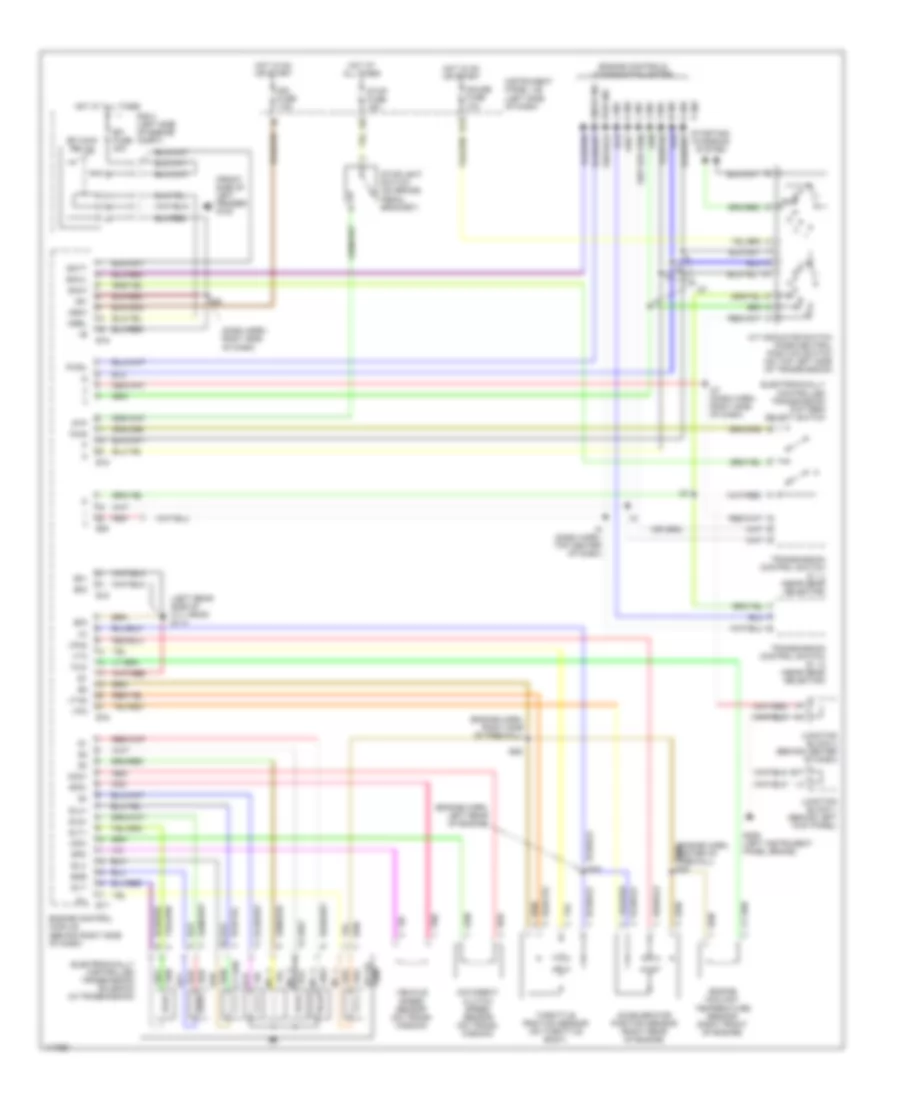
TRANSMISSION
A/T Wiring Diagram for Lexus SC 400 1999
List of elements for A/T Wiring Diagram for Lexus SC 400 1999:
- (dash harn, right side of dash)
- (engine harn, left rear of engine)
- (engine harn, right side of firewall)
- (front side of left fender) g100
- (left rear side of cyl head) g114
- +b1
- 2 ind
- 3 ind
- 4 ind
- A/t indicator switch (park/neutral position switch (on top left side of transmission)
- A/t oil
- Accelerator position sensor (right rear of engine)
- Batt
- D ind
- E01
- E02
- E03
- E15
- E16
- E17
- E18
- E19
- E20
- E26
- E29
- Efi fuse 30a
- Efi main relay
- Electronically controlled transmission pattern select switch
- Electronically controlled transmission solenoid (in transmission)
- Engine control module (behind right side of dash)
- Engine controls (combination meter)
- Engine coolant temperature sensor (right front of engine)
- G206 (left instrument panel brace)
- Gauge fuse 10a
- H12
- Hot at all times
- Hot in on or start
- I10
- I25
- I27
- I27 (dash harn, right side of dash)
- I9 (dash harn, top center of dash)
- Ign fuse 7.5a
- Igsw
- Instrument panel j/b (left side of dash)
- Junction block 1 (behind left kick panel)
- Junction block 3 (behind center of dash)
- L ind
- Mrel
- N ind
- Nco+
- Nco-
- No. 1
- No. 2
- No. 3
- No. 4
- O/d direct clutch speed sensor (on trans- mission)
- Oil
- P ind
- Pnk
- Pwr
- Pwr ind
- Pwrl
- R ind
- R n
- R/b 2 (left side of engine compt)
- Red
- Sln
- Sln+
- Sln- sln-
- Slt
- Slt+
- Slt-
- Slu
- Slu+
- Slu-
- Snow ind
- Snwi
- Snwl
- Sp2+
- Sp2-
- Starting/ charging system
- Stop fuse 15a
- Stoplight switch (on brake pedal bracket)
- Stp
- Temp
- Throttle position sensor (on throttle body)
- Thw
- Transmission control switch (2 - l) (near gear selector)
- Transmission control switch (d - 4) (near gear selector)
- Vehicle speed sensor (on trans- mission)
- Vpa
- Vpa2
- Vta
- Vta2
 Čeština
 Dansk
Dansk Deutsch
 Ελληνικά
 English
 Español
 Suomi
Suomi Français
 Français
 עברית
עברית Hrvatski
 Magyar
 Italiano
 日本語
日本語 한국어
한국어 Nederlands
 Polski
 Português
 Português
 Română
 Русский
 Slovenčina
 Slovenščina
 Svenska
 Türkçe
 中文 (中国)
 English