TRANSMISSION
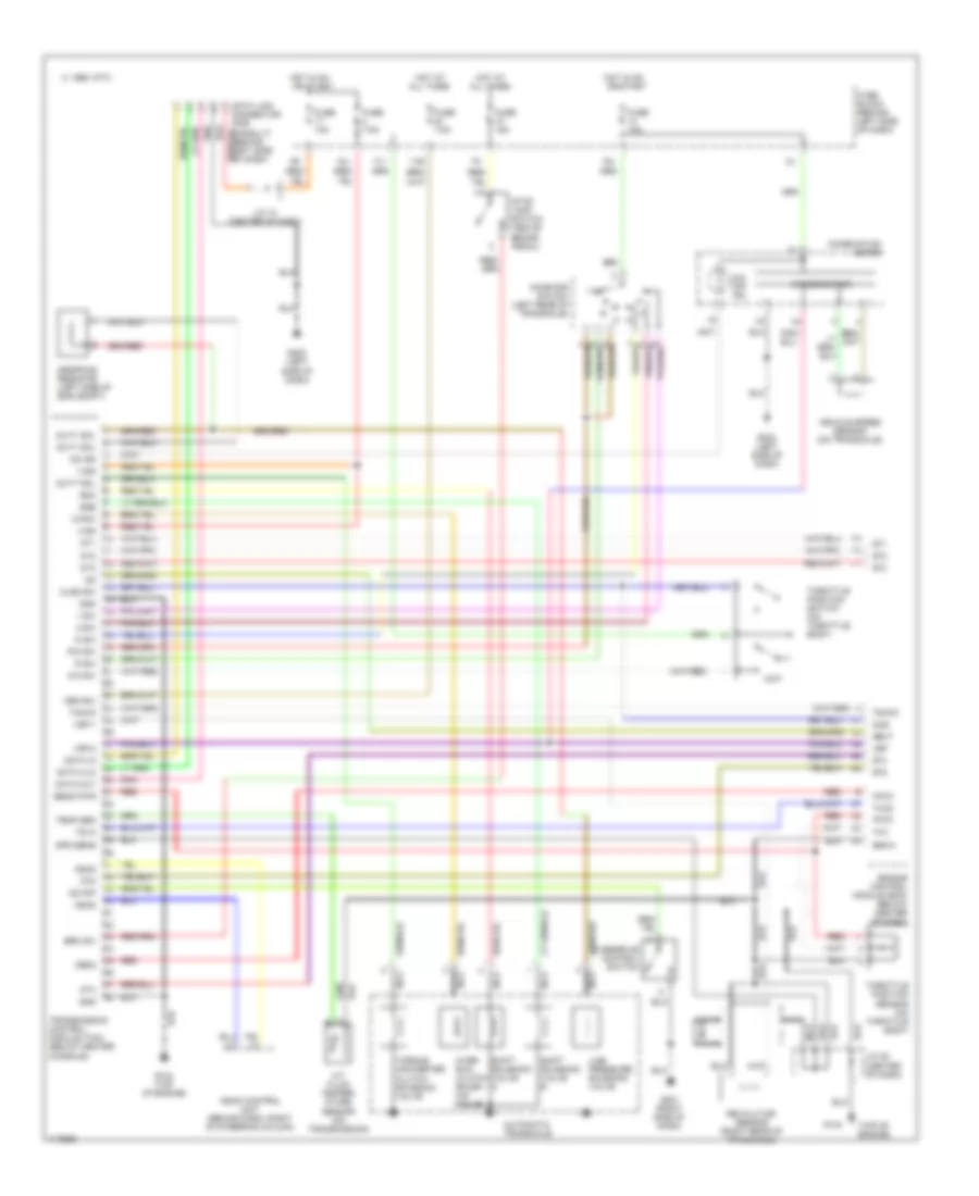
A/T Wiring Diagram for Nissan Maxima GXE 1998
List of elements for A/T Wiring Diagram for Nissan Maxima GXE 1998:
- (top of engine)
- 1 sw
- 13g
- 17j
- 18j
- 1995 vftc c
- 19j
- 2 sw
- A/t fluid temper- ature sensor (on transmission)
- All times
- Ascd
- Ascd control unit (behind dash, right of steering column)
- Atck
- Automatic transaxle
- Avcc
- Brk sw
- Clsd sw
- Combination meter
- D sw
- Data clk
- Data in
- Data link connector (for consult) (behind left side of dash)
- Data out
- Dropping resistor (left side of eng compt)
- Dt1
- Dt2
- Dt3
- Dt4
- Dt5
- Duty sol
- Engine control module (ecm) (below center of dash)
- Fuse 10a
- Fuse 15a
- Fuse 7.5a
- Fuse block (behind left side of dash)
- G134
- G134 (top of engine)
- G201 (right side of dash)
- G202 (left side of dash)
- Gnd
- Gnd-a
- Hot at
- Hot in on or start
- Idle
- Inhibitor switch (left rear of transaxle)
- J/c 10 (center of dash)
- J/c 25 (center of dash)
- Line pressure solenoid valve
- Mem b/u
- Nca
- Neut
- O/d off ind
- Obd2
- Od ind
- Od off
- Over- run clutch solen- oid valve
- Overdrive control switch
- Ovr/c
- P/n sw
- Pnk
- R sw
- Red
- Revolution sensor (right rear of transaxle)
- Sens pwr
- Shift solenoid valve a
- Shift solenoid valve b
- Spd sens
- Speedometer
- Ssa
- Ssb
- Stop lamp switch (above brake pedal)
- Tacho
- Temp sen
- Throttle position sensor (on throttle body)
- Throttle position switch (on throttle body)
- Torque converter clutch solenoid valve
- Transmission control module (tcm) (below center console)
- Ts in
- Tvo
- Tvoo
- Vehicle speed sensor (on transaxle)
- Vign
- Vsp
- Vsp-1
- Vsp-2
- Wo sw
- Wot
 Čeština
 Dansk
Dansk Deutsch
 Ελληνικά
 English
 Español
 Suomi
Suomi Français
 Français
 עברית
עברית Hrvatski
 Magyar
 Italiano
 日本語
日本語 한국어
한국어 Nederlands
 Polski
 Português
 Português
 Română
 Русский
 Slovenčina
 Slovenščina
 Svenska
 Türkçe
 中文 (中国)
 English