TRANSMISSION
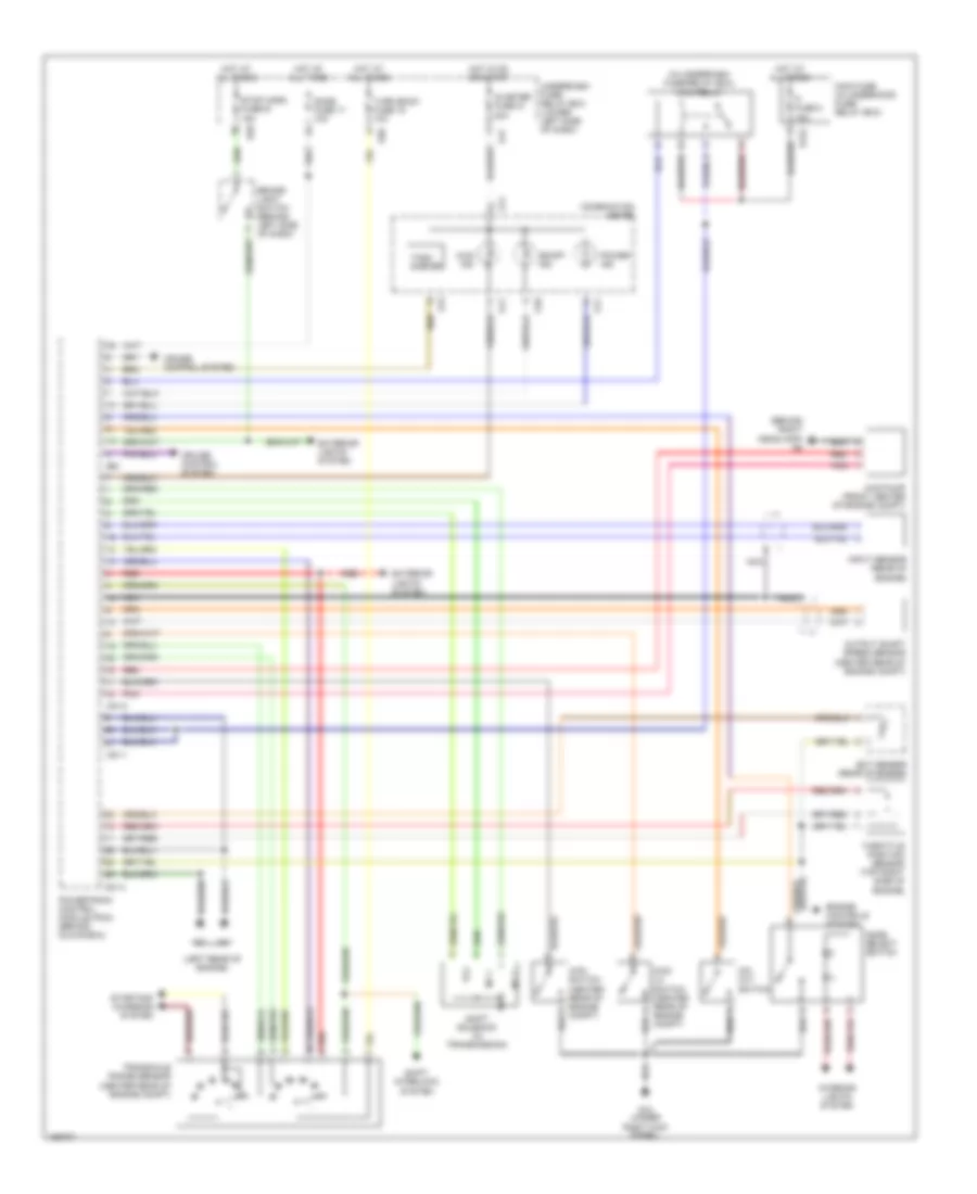
A/T Wiring Diagram for Suzuki Vitara 2004
List of elements for A/T Wiring Diagram for Suzuki Vitara 2004:
- (behind right headlamp) g8
- (in underdash fuse/relay box) main relay
- (left rear of engine)
- 4wd ind
- 4wd lo switch (center rear of engine compt)
- 4wd pump (front center of engine compt)
- 4wd switch (center rear of engine compt)
- Brake- light switch (behind left side of dash)
- C51-1
- C51-2
- C51-3
- Combination meter
- Cruise control system
- Dome fuse 17 10a
- E122
- E28
- E61
- Ect sensor (rear of engine)
- Engine controls system
- Exterior lights system
- Fi fuse 8 15a
- G10
- G10 (under right kick panel)
- G11
- G12
- G17
- Hot at all times
- Hot in on or start
- Ig meter fuse 21 20a
- Input sensor (rear of engine)
- Interior lights system
- Main fuse (in underhood fuse/ relay box)
- Mode select switch
- N r
- Nca
- No 1
- No 2
- O/d cut switch
- Od/off ind
- Output shaft speed sensor (center rear of engine compt)
- Pnk
- Power ind
- Powertrain control module (pcm) (behind glove box)
- Red
- Shift interlock system
- Shift solenoid (in transmission)
- Starting/ charging system
- Stop horn fuse16 15a
- Tach- ometer
- Tcc
- Throttle position sensor (top right side of engine)
- Transaxle range sensor (center rear of engine compt)
- Turn back fuse 19 10a
- Underdash fuse/ relay box (lower left side of dash)
 Čeština
 Dansk
Dansk Deutsch
 Ελληνικά
 English
 English
 Español
 Suomi
Suomi Français
 עברית
עברית Hrvatski
 Magyar
 Italiano
 日本語
日本語 한국어
한국어 Nederlands
 Polski
 Português
 Português
 Română
 Русский
 Slovenčina
 Slovenščina
 Svenska
 Türkçe
 中文 (中国)
 Français