TRANSMISSION
2.7L
2.7L, A/T Wiring Diagram for Toyota T100 SR5 1997
 https://portal-diagnostov.com/license.html
Automotive Electricians Portal FZCO
Automotive Electricians Portal FZCO
https://portal-diagnostov.com/license.html
https://portal-diagnostov.com/license.html
Automotive Electricians Portal FZCO
Automotive Electricians Portal FZCO
List of elements for 2.7L, A/T Wiring Diagram for Toyota T100 SR5 1997:
- (dash harn, right kick panel)
- 2 ind
- A/t indicator (p/n position) switch (under central trans tunnel)
- A/t oil temperature sensor (on transmission)
- Batt (b+)
- C17
- Cig fuse 15a
- Computer data lines system
- Cruise control system
- D ind
- Diode (behind right dash)
- E1 (grd)
- Efi fuse 15a
- Efi main
- Electronic controlled transmission solenoids
- Engine control module (below right side of dash)
- Engine coolant temperature sensor (on engine)
- G100 (front of left front fender)
- G110 (left front of engine)
- G200 (left kick panel)
- Gauge fuse 10a
- Hot at all times
- Hot in acc or run
- Hot in run or start
- I12
- I14
- I14 (dash harn, right kick panel)
- Idl
- Ign fuse 7.5a
- Instrument cluster system
- Integration relay
- J/b 1 (left kick panel)
- L ind
- N ind
- Nca
- No. 1
- No. 2
- No. 3
- O/d main switch
- O/d off
- Od2
- Oil
- P ind
- R ind
- R/b 2 (left side of engine compt)
- Red
- Relay
- Sp1
- Sp2+
- Sp2-
- Speedo
- Stop fuse 10a
- Stoplamp switch (brake pedal bracket)
- Te1
- Throttle position sensor (top left side of eng)
- Thw
- Vcc
- Vehicle speed sensor (for ect) (on transmission)
- Vta
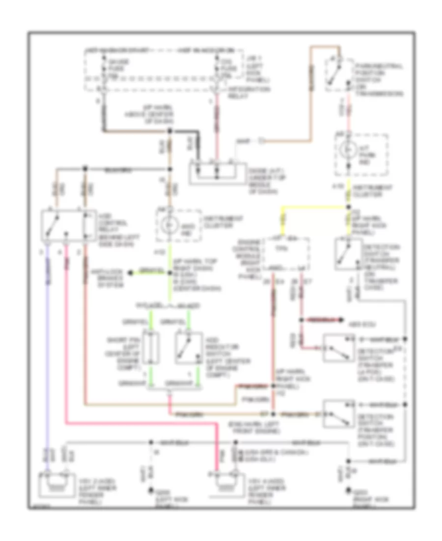
4WD Wiring Diagram, A/T for Toyota T100 SR5 1997
List of elements for 4WD Wiring Diagram, A/T for Toyota T100 SR5 1997:
- (behind left side dash)
- (eng harn, left front engine)
- (i/p harn, above center of dash)
- (i/p harn, right kick panel) i12
- (i/p harn, top right dash) i9 (usa) i6 (can) (center dash)
- (left kick panel)
- 4wd
- 4wd ind
- A/t park ind
- A12
- Abs ecu
- Add control relay
- Add indicator switch (left center of engine compt)
- Anti-lock brakes system
- Cig fuse 15a
- Detection switch (transfer l4 pos) (on t-case)
- Detection switch (transfer neutral) (on transfer case)
- Detection switch (transfer positon) (on t-case)
- Diode (a/t) (under top middle of dash)
- Engine control module (right kick panel)
- G200 (left kick panel)
- G203 (right kick panel)
- Gauge fuse 10a
- Hot in acc or on
- Hot in on or start
- I1 (usa-sr5 & canada) i6 (usa-dlx)
- Instrument cluster
- Integration relay
- J/b 1
- Park/neutral position switch (on transmission)
- Pnk
- Red/
- Short pin (left center of engine compt)
- Tfn
- Vsv 2 (add) (left inner fender panel)
- Vsv 4 (add) (left inner fender panel)
- W/ add
- W/o add
4WD Wiring Diagram, M/T for Toyota T100 SR5 1997
List of elements for 4WD Wiring Diagram, M/T for Toyota T100 SR5 1997:
- (i/p harn, right kick panel) i12
- 4wd
- 4wd indic.
- A12
- Abs ecu
- Add control relay (left side of dash)
- Add indicator switch (left middle of engine compt)
- Anti-lock brakes system (abs ecu)
- Detection switch (tranfer l4 position) (on transfer case)
- Detection switch (tranfer position) (on transfer case)
- E8 (eng harn, left side of engine)
- Engine control module (right kick panel)
- G200 (left kick panel)
- G203 (right kick panel)
- Gauge fuse 10a
- Hot in on or start
- I1 (dlx grade) i6 (sr5 grade and canada)
- I4 (sr5 grade and canada)
- I6 (dlx grade) i1 (sr5 grade and canada)
- I6 (sr5 grade and canada) (i/p harn, above center of dash)
- I7 (dlx grade)
- I9 (dlx grade)
- Instrument cluster
- Integration relay
- J/b 1 (left kick panel)
- Of dash)
- Pnk
- Short pin (left middle of engine compt)
- Vsv 2 (add) (left inner fender panel)
- Vsv 4 (add) (left inner fender panel)
- W/ add
- W/o add
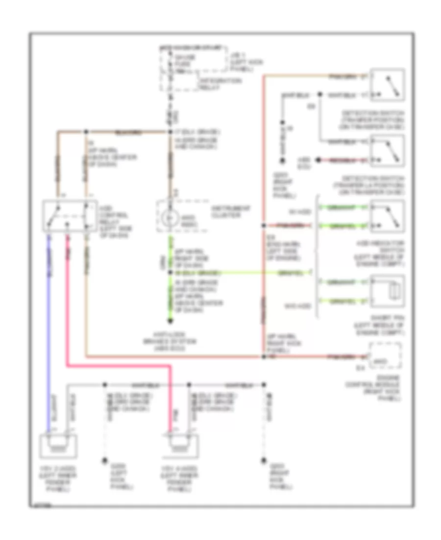
Transfer Case Wiring Diagram, A/T for Toyota T100 SR5 1997
List of elements for Transfer Case Wiring Diagram, A/T for Toyota T100 SR5 1997:
- (behind left side dash)
- (eng harn, left front engine)
- (i/p harn, above center of dash)
- (i/p harn, right kick panel) i12
- (i/p harn, top right dash) i9 (usa) i6 (can) (center dash)
- (left kick panel)
- 4wd
- 4wd ind
- A/t park ind
- A12
- Abs ecu
- Add control relay
- Add indicator switch (left center of engine compt)
- Anti-lock brakes system
- Cig fuse 15a
- Detection switch (transfer l4 pos) (on t-case)
- Detection switch (transfer neutral) (on transfer case)
- Detection switch (transfer positon) (on t-case)
- Diode (a/t) (under top middle of dash)
- Engine control module (right kick panel)
- G200 (left kick panel)
- G203 (right kick panel)
- Gauge fuse 10a
- Hot in acc or on
- Hot in on or start
- I1 (usa-sr5 & canada) i6 (usa-dlx)
- Instrument cluster
- Integration relay
- J/b 1
- Park/neutral position switch (on transmission)
- Pnk
- Red/
- Short pin (left center of engine compt)
- Tfn
- Vsv 2 (add) (left inner fender panel)
- Vsv 4 (add) (left inner fender panel)
- W/ add
- W/o add
Transfer Case Wiring Diagram, M/T for Toyota T100 SR5 1997
List of elements for Transfer Case Wiring Diagram, M/T for Toyota T100 SR5 1997:
- (i/p harn, right kick panel) i12
- 4wd
- 4wd indic.
- A12
- Abs ecu
- Add control relay (left side of dash)
- Add indicator switch (left middle of engine compt)
- Anti-lock brakes system (abs ecu)
- Detection switch (tranfer l4 position) (on transfer case)
- Detection switch (tranfer position) (on transfer case)
- E8 (eng harn, left side of engine)
- Engine control module (right kick panel)
- G200 (left kick panel)
- G203 (right kick panel)
- Gauge fuse 10a
- Hot in on or start
- I1 (dlx grade) i6 (sr5 grade and canada)
- I4 (sr5 grade and canada)
- I6 (dlx grade) i1 (sr5 grade and canada)
- I6 (sr5 grade and canada) (i/p harn, above center of dash)
- I7 (dlx grade)
- I9 (dlx grade)
- Instrument cluster
- Integration relay
- J/b 1 (left kick panel)
- Of dash)
- Pnk
- Short pin (left middle of engine compt)
- Vsv 2 (add) (left inner fender panel)
- Vsv 4 (add) (left inner fender panel)
- W/ add
- W/o add
3.4L
3.4L, A/T Wiring Diagram for Toyota T100 SR5 1997
List of elements for 3.4L, A/T Wiring Diagram for Toyota T100 SR5 1997:
- (dash harn, center of dash)
- (dash harn, right kick panel)
- (dash harn, right side of dash)
- (engine harn, left front of engine)
- 2 ind
- 4wd
- 4wd ind
- A/t indicator (p/n position) switch (under central trans tunnel)
- A/t oil temperature sensor (on transmission)
- Add indicator switch or add jumper pin (left rear of engine compt)
- Batt (b+)
- C17
- Cig fuse 15a
- Cruise control actuator with ecu (right side of engine compt)
- D ind
- Data link connector (left side of engine)
- Diode (behind right side of dash)
- E1 (grd)
- Ect
- Efi fuse 15a
- Efi main
- Electronic controlled transmission solenoids
- Engine control module (below right side of dash, near panel)
- Engine coolant temperature sensor (on engine)
- G100 (front of left front fender)
- G110 (left front of engine)
- G200 (left kick panel)
- Gauge fuse 10a
- Hot at all times
- Hot in acc or run
- Hot in run or start
- I12
- I14
- I14 (dash harness, right kick panel)
- I5 (or i6)
- I5 (or i7) (dash harn, left side of dash)
- I6 (or i7)
- Idl
- Ign fuse 7.5a
- Instrument cluster system
- Integration relay
- J/b 1 (left kick panel)
- L ind
- N ind
- Nca
- No. 1
- No. 2
- No. 3
- O/d main switch
- O/d off
- Od1
- Od2
- Oil
- Oil temp
- Oilw
- P ind
- R ind
- R/b 2 (left side of engine compt)
- Relay
- Sp2
- Spd
- Speedo
- Stop fuse 10a
- Stoplamp switch (on brake pedal bracket)
- Te1
- Throttle position sensor (top rt side of eng)
- Thw
- Transfer case position detection switch (transfer case)
- Transfer l4 position detection switch (transfer case)
- Vcc
- Vehicle speed sensor (for ect) (on transmission)
- Vta
4WD Wiring Diagram, A/T for Toyota T100 SR5 1997
List of elements for 4WD Wiring Diagram, A/T for Toyota T100 SR5 1997:
- (behind left side dash)
- (eng harn, left front engine)
- (i/p harn, above center of dash)
- (i/p harn, right kick panel) i12
- (i/p harn, top right dash) i9 (usa) i6 (can) (center dash)
- (left kick panel)
- 4wd
- 4wd ind
- A/t park ind
- A12
- Abs ecu
- Add control relay
- Add indicator switch (left center of engine compt)
- Anti-lock brakes system
- Cig fuse 15a
- Detection switch (transfer l4 pos) (on t-case)
- Detection switch (transfer neutral) (on transfer case)
- Detection switch (transfer positon) (on t-case)
- Diode (a/t) (under top middle of dash)
- Engine control module (right kick panel)
- G200 (left kick panel)
- G203 (right kick panel)
- Gauge fuse 10a
- Hot in acc or on
- Hot in on or start
- I1 (usa-sr5 & canada) i6 (usa-dlx)
- Instrument cluster
- Integration relay
- J/b 1
- Park/neutral position switch (on transmission)
- Pnk
- Red/
- Short pin (left center of engine compt)
- Tfn
- Vsv 2 (add) (left inner fender panel)
- Vsv 4 (add) (left inner fender panel)
- W/ add
- W/o add
4WD Wiring Diagram, M/T for Toyota T100 SR5 1997
List of elements for 4WD Wiring Diagram, M/T for Toyota T100 SR5 1997:
- (i/p harn, right kick panel) i12
- 4wd
- 4wd indic.
- A12
- Abs ecu
- Add control relay (left side of dash)
- Add indicator switch (left middle of engine compt)
- Anti-lock brakes system (abs ecu)
- Detection switch (tranfer l4 position) (on transfer case)
- Detection switch (tranfer position) (on transfer case)
- E8 (eng harn, left side of engine)
- Engine control module (right kick panel)
- G200 (left kick panel)
- G203 (right kick panel)
- Gauge fuse 10a
- Hot in on or start
- I1 (dlx grade) i6 (sr5 grade and canada)
- I4 (sr5 grade and canada)
- I6 (dlx grade) i1 (sr5 grade and canada)
- I6 (sr5 grade and canada) (i/p harn, above center of dash)
- I7 (dlx grade)
- I9 (dlx grade)
- Instrument cluster
- Integration relay
- J/b 1 (left kick panel)
- Of dash)
- Pnk
- Short pin (left middle of engine compt)
- Vsv 2 (add) (left inner fender panel)
- Vsv 4 (add) (left inner fender panel)
- W/ add
- W/o add
Transfer Case Wiring Diagram, A/T for Toyota T100 SR5 1997
List of elements for Transfer Case Wiring Diagram, A/T for Toyota T100 SR5 1997:
- (behind left side dash)
- (eng harn, left front engine)
- (i/p harn, above center of dash)
- (i/p harn, right kick panel) i12
- (i/p harn, top right dash) i9 (usa) i6 (can) (center dash)
- (left kick panel)
- 4wd
- 4wd ind
- A/t park ind
- A12
- Abs ecu
- Add control relay
- Add indicator switch (left center of engine compt)
- Anti-lock brakes system
- Cig fuse 15a
- Detection switch (transfer l4 pos) (on t-case)
- Detection switch (transfer neutral) (on transfer case)
- Detection switch (transfer positon) (on t-case)
- Diode (a/t) (under top middle of dash)
- Engine control module (right kick panel)
- G200 (left kick panel)
- G203 (right kick panel)
- Gauge fuse 10a
- Hot in acc or on
- Hot in on or start
- I1 (usa-sr5 & canada) i6 (usa-dlx)
- Instrument cluster
- Integration relay
- J/b 1
- Park/neutral position switch (on transmission)
- Pnk
- Red/
- Short pin (left center of engine compt)
- Tfn
- Vsv 2 (add) (left inner fender panel)
- Vsv 4 (add) (left inner fender panel)
- W/ add
- W/o add
Transfer Case Wiring Diagram, M/T for Toyota T100 SR5 1997
List of elements for Transfer Case Wiring Diagram, M/T for Toyota T100 SR5 1997:
- (i/p harn, right kick panel) i12
- 4wd
- 4wd indic.
- A12
- Abs ecu
- Add control relay (left side of dash)
- Add indicator switch (left middle of engine compt)
- Anti-lock brakes system (abs ecu)
- Detection switch (tranfer l4 position) (on transfer case)
- Detection switch (tranfer position) (on transfer case)
- E8 (eng harn, left side of engine)
- Engine control module (right kick panel)
- G200 (left kick panel)
- G203 (right kick panel)
- Gauge fuse 10a
- Hot in on or start
- I1 (dlx grade) i6 (sr5 grade and canada)
- I4 (sr5 grade and canada)
- I6 (dlx grade) i1 (sr5 grade and canada)
- I6 (sr5 grade and canada) (i/p harn, above center of dash)
- I7 (dlx grade)
- I9 (dlx grade)
- Instrument cluster
- Integration relay
- J/b 1 (left kick panel)
- Of dash)
- Pnk
- Short pin (left middle of engine compt)
- Vsv 2 (add) (left inner fender panel)
- Vsv 4 (add) (left inner fender panel)
- W/ add
- W/o add

 Čeština
 Dansk
Dansk Deutsch
 Ελληνικά
 English
 Español
 Suomi
Suomi Français
 Français
 עברית
עברית Hrvatski
 Magyar
 Italiano
 日本語
日本語 한국어
한국어 Nederlands
 Polski
 Português
 Português
 Română
 Русский
 Slovenčina
 Slovenščina
 Svenska
 Türkçe
 中文 (中国)