TRANSMISSION
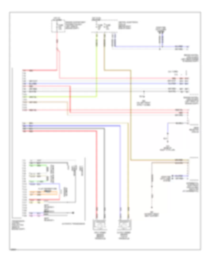
Transmission Wiring Diagram for Volvo V50 2010
List of elements for Transmission Wiring Diagram for Volvo V50 2010:
- 2.4l
- 2.5l turbo
- A10
- A11
- A12
- A13
- A14
- A15
- A16
- Automatic transmission
- B13
- B15
- B16
- B44
- B54
- B57
- Brake control module (bcm) (left rear corner of engine compt)
- C10
- C11
- C12
- C13
- C14
- C15
- C16
- C17
- C18
- C19
- C20
- C21
- C22
- C38
- Central electronic module (behind right side of dash)
- Computer data lines system
- Differential electronic module (dem) (s40 & v50) (at differential)
- Engine compartment distribution box (left side of engine compt)
- Engine control module (ecm) (left front of engine compt)
- Fluid temperature sensor
- Fuse f23 10a
- Fuse f51 10a
- Fuse f52 5a
- G10 (base of right "a" pillar)
- G14
- G15
- G52 (on left front strut tower)
- G67 (on right front seat support)
- Gear selector module
- Hot at all times
- Hot in on or start
- Input speed sensor (rear of transaxle)
- Otg
- Output speed sensor (top of transaxle)
- Red
- Shift solenoid 1
- Shift solenoid 3
- Shift solenoid 4
- Shift solenoid 5
- Sls
- Slsg
- Slt
- Sltg
- Slu
- Slug
- Solenoid 2 shift
- Solenoid lock-up
- Solenoid pressure
- Solenoid throttle
- Sp1+
- Sp1-
- Sp2+
- Sp2-
- Transmission control module (tcm) (rear of engine compt)
 Čeština
 Dansk
Dansk Deutsch
 Ελληνικά
 English
 Español
 Suomi
Suomi Français
 Français
 עברית
עברית Hrvatski
 Magyar
 Italiano
 日本語
日本語 한국어
한국어 Nederlands
 Polski
 Português
 Português
 Română
 Русский
 Slovenčina
 Slovenščina
 Svenska
 Türkçe
 中文 (中国)
 English