AUTOMOTIVE ELECTRICIANS PORTAL

WARNING SYSTEMS – Acura TL 2012 – SYSTEM WIRING DIAGRAMS

WARNING SYSTEMS

Chime Wiring Diagram for Acura TL 2012

Chime Wiring Diagram for Acura TL 2012 https://portal-diagnostov.com/license.html
https://portal-diagnostov.com/license.html Automotive Electricians Portal FZCO Automotive Electricians Portal FZCO
Download PDF file

List of elements for Chime Wiring Diagram for Acura TL 2012:

  • (behind left side of dash) driver's junction box 2
  • A16
  • A17
  • A48
  • A49
  • Auto
  • B19
  • Beeper
  • Brake system ind
  • C14
  • C405
  • C45
  • C701
  • Can h
  • Can l
  • Center junction box (under left side of dash)
  • Circuit dimming
  • Combination light switch
  • Computer data lines system
  • Control circuits
  • Control speaker
  • D12
  • Door/trunk lid open ind
  • Driver's door switch
  • Driver's junction box 1 (behind left side of dash)
  • Driver's micu
  • Driver's seat belt buckle switch (in driver's seat belt buckle)
  • Driver's under-dash fuse/relay box (under left end of dash)
  • E10
  • Ecm (right side of engine compt)
  • F can hi
  • F can lo
  • F29
  • Flbc
  • Fr door sw l
  • Fuse 10a
  • Fuse 7.5a
  • G401 (behind left side of dash)
  • G403 (behind middle of dash)
  • G701 (under driver's seat)
  • Gauge control module
  • Gnd
  • Head
  • Headlight switch
  • Hot at all times
  • Hot in on or start
  • Ig1
  • Ignition key light
  • Ignition key switch
  • Ignition key switch/key light
  • Indicator
  • Key lt-
  • Key sw
  • Lights on ind
  • Low oil pressure ind
  • Network transceiver fast controller area
  • Off
  • Oil pressure switch (under front of engine)
  • Opsw
  • P19
  • P20
  • Park
  • Parking brake switch (on park brake lever bracket)
  • Picu key
  • Pnk
  • Power control unit (under left side of dash)
  • Q11
  • Q18
  • Red
  • Remote slot control unit (behind right side of dash)
  • Seat belt reminder ind
  • Small sw
  • Srs unit (under lower middle of dash)
  • Transceiver area network controller body
  • Under-hood fuse/relay box (left rear of engine compt)
  • W/ keyless access
  • W/o keyless access

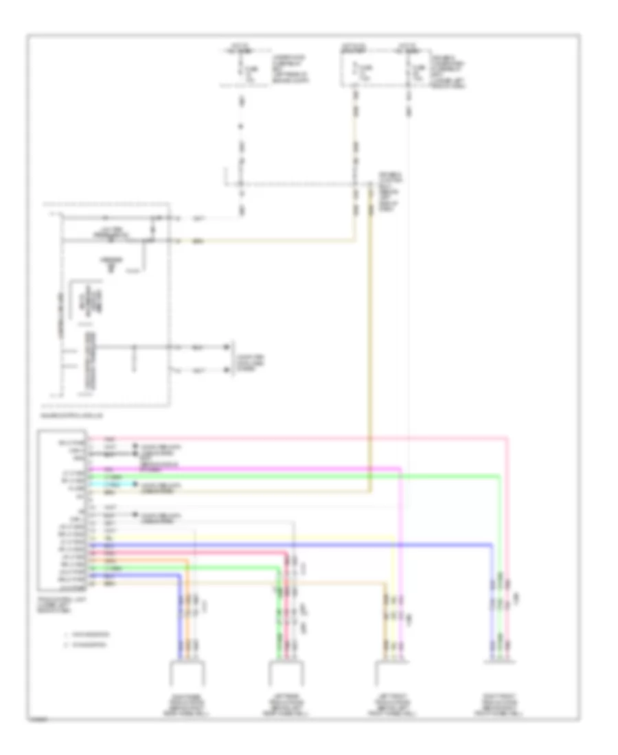
Tire Pressure Monitoring Wiring Diagram for Acura TL 2012

Tire Pressure Monitoring Wiring Diagram for Acura TL 2012 https://portal-diagnostov.com/license.html
https://portal-diagnostov.com/license.html Automotive Electricians Portal FZCO Automotive Electricians Portal FZCO
Get access to all wiring diagrams of the carDownload PDF file

List of elements for Tire Pressure Monitoring Wiring Diagram for Acura TL 2012:

  • (mid) unit
  • C206
  • C306
  • C411
  • C601
  • Can h
  • Can l
  • Computer data lines system
  • Computer data lines system g403 (behind middle of dash)
  • Control circuits
  • Display information multi-
  • Driver's junction box 1 (behind left side of dash)
  • Driver's under-dash fuse/relay box (under left end of dash)
  • E10
  • Fast controller area network transceiver
  • Fuse 10a
  • Fuse 7.5a
  • Gauge control module
  • Gnd
  • Hot at all times
  • Hot in on or start
  • Ig1
  • K-line
  • Left front tpms initiator (behind left front wheelwell)
  • Left rear tpms initiator (behind left rear wheelwell)
  • Lf lf gnd
  • Lf lf pwr
  • Lf lf sig
  • Low tire pressure ind
  • Lr lf gnd
  • Lr lf pwr
  • Lr lf sig
  • Message ind
  • N14
  • P20
  • Pnk
  • Rf lf gnd
  • Rf lf pwr
  • Rf lf sig
  • Right front tpms initiator (behind right front wheelwell)
  • Right rear tpms initiator (behind right rear wheelwell)
  • Rr lf gnd
  • Rr lf pwr
  • Rr lf sig
  • Tpms control unit (under left side of dash)
  • Under-hood fuse/relay box (left rear of engine compt)
  • W/ navigation
  • W/o navigation