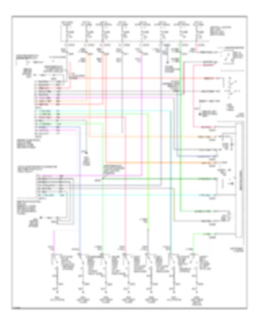
WARNING SYSTEMS
Warning Systems Wiring Diagram for Ford Escape 2004
List of elements for Warning Systems Wiring Diagram for Ford Escape 2004:
- (behind center of dash)
- (behind left side of dash) g203
- (in main harness, near breakout to c211) s2001
- (near breakout to evap canister vent control solenoid)
- (near breakout to restraints control module)
- (w/ autolamps) s2000
- 0 off 1 park 2 head
- Air bag ind
- C201a
- C201b
- C2041a
- C220a
- C220b
- C220c
- C270c
- C270d
- C270e
- Central junction box (cjb) (below left end of dash)
- Door ajar ind
- Driver side front door lock unit (in left front door)
- Electrochromatic inside mirror unit
- Fuse 10a
- Fuse 30a
- Fuse 5a
- G201
- G201 (behind center of dash)
- G300 (left front floor)
- G301 (left front floor)
- G401 (in liftgate)
- G402 (left rear end of vehicle)
- Generic electronic module (gem) (behind lower center of dash)
- Hot at all times
- Hot in run or acc
- Hot in start or run
- Ignition switch
- Instrument cluster
- Key in ignition switch
- Left rear door lock actuator (in left rear door)
- Liftgate ajar switch (in bottom center of liftgate)
- Liftgate glass ajar switch (in center of liftgate)
- Light switch
- Microprocessor
- Note: shorting bar is connected between pins: 20 & 21 conn. c2041a
- Passenger side front door lock unit (in right front door)
- Power distribution system
- Restraints control module (beneath lower center of dash, on transmission tunnel)
- Right rear door lock actuator (in right rear door)
- S2002
- S205
- S208
- S212
- S215
- S216
- S220
- S222
- S302
- S309
- S311
- S401
- S500
- S600
- Safety belt ind
- Safety belt switch (at base of left "b" pillar)
- W/ autolamps
 Čeština
 Dansk
Dansk Deutsch
 Ελληνικά
 English
 Español
 Suomi
Suomi Français
 Français
 עברית
עברית Hrvatski
 Magyar
 Italiano
 日本語
日本語 한국어
한국어 Nederlands
 Polski
 Português
 Português
 Română
 Русский
 Slovenčina
 Slovenščina
 Svenska
 Türkçe
 中文 (中国)
 English