AUTOMOTIVE ELECTRICIANS PORTAL

WARNING SYSTEMS – Ford Explorer 2011 – SYSTEM WIRING DIAGRAMS

WARNING SYSTEMS

Chime Wiring Diagram for Ford Explorer 2011

Chime Wiring Diagram for Ford Explorer 2011 https://portal-diagnostov.com/license.html
https://portal-diagnostov.com/license.html Automotive Electricians Portal FZCO Automotive Electricians Portal FZCO
Download PDF file

List of elements for Chime Wiring Diagram for Ford Explorer 2011:

  • Body control module (bcm) (left end of dash)
  • Brake fluid level switch (on master cylinder)
  • Brk fluid sw
  • Brk fluid sw rtn
  • C2280a
  • C2280b
  • C2280c
  • C2280f
  • C2414a
  • C310a
  • C310b
  • C311
  • C3138
  • C3139
  • C316
  • C327
  • C4174a
  • C4174b
  • C934
  • Cbp31
  • Cdc30
  • Cmc19
  • Cmc25
  • Computer data lines system
  • Cpl26
  • Cpl31
  • Cpl36
  • Cpl39
  • Cpl58
  • Cr201
  • Driv buckle sw
  • Driver safety belt buckle switch (under driver's seat)
  • Fuse 10a
  • Fuse 15a
  • G103 (left front corner of engine compt)
  • G300 (left kick panel)
  • G301 (left rear quarter panel)
  • G302 (right rear quarter panel)
  • Gd349
  • Gnd
  • Hot at all times
  • Hot in start or run
  • Hs can +
  • Hs can -
  • Hs can+
  • Hs can-
  • Ignition switch (w/o intelligent access)
  • Instrument panel cluster (ipc)
  • Key in
  • Key in ignition
  • Left front door latch (driver's door)
  • Left rear door latch (left rear door)
  • Lf door ajar
  • Liftgate ajar
  • Liftgate latch (lower center of liftgate)
  • Liftgate/ trunk module (base of left "d" pillar)
  • Lr door ajar
  • Micro
  • Ms can +
  • Ms can -
  • Multi- function switch
  • Nca
  • Park brk
  • Parking brake switch (left kick panel)
  • Restraints control module (rcm) (under center console)
  • Rf door ajar
  • Right front door latch (front passenger's door)
  • Right rear door latch (right rear door)
  • Rmc19
  • Rr door ajar
  • Run/start
  • S353
  • S410
  • S501
  • S602
  • S700
  • S800
  • Steering column control module (sccm) (top of steering column)
  • Vdb04
  • Vdb05
  • Vdb06
  • Vdb07
  • W/ manual liftgate
  • W/ power liftgate

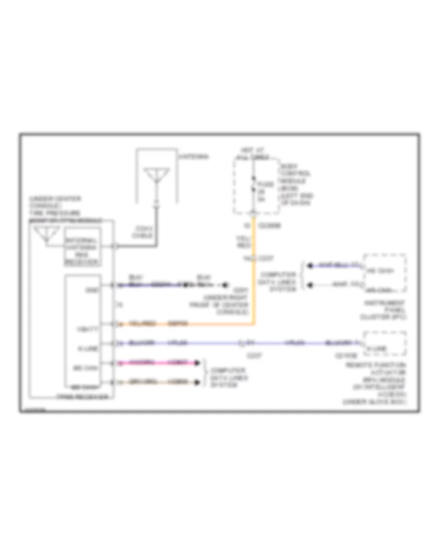
Tire Pressure Monitoring Wiring Diagram for Ford Explorer 2011

Tire Pressure Monitoring Wiring Diagram for Ford Explorer 2011 https://portal-diagnostov.com/license.html
https://portal-diagnostov.com/license.html Automotive Electricians Portal FZCO Automotive Electricians Portal FZCO
Get access to all wiring diagrams of the carDownload PDF file

List of elements for Tire Pressure Monitoring Wiring Diagram for Ford Explorer 2011:

  • (under center console) tire pressure monitor (tpm) module
  • Antenna
  • Body control module (bcm) (left end of dash)
  • C2153e
  • C2280b
  • C237
  • Coax cable
  • Computer data lines system
  • Fuse 5a
  • G201 (under right front of center console)
  • Gd214
  • Gnd
  • Hot at all times
  • Hs can+
  • Hs can-
  • Instrument panel cluster (ipc)
  • Internal antenna rke receiver
  • K-line
  • Ms can+
  • Ms can-
  • Remote function actuator (rfa) module (w/ intelligent access) (under glove box)
  • S392
  • Sbp06
  • Tpms receiver
  • Vbatt
  • Vdb06
  • Vdb07
  • Vpl56