WARNING SYSTEMS
Chime Wiring Diagram for Ford Mustang 2010
 https://portal-diagnostov.com/license.html
Automotive Electricians Portal FZCO
Automotive Electricians Portal FZCO
https://portal-diagnostov.com/license.html
https://portal-diagnostov.com/license.html
Automotive Electricians Portal FZCO
Automotive Electricians Portal FZCO
List of elements for Chime Wiring Diagram for Ford Mustang 2010:
- (body main harness, near breakout to g101)
- (body main harness, near breakout to c919)
- (dash panel to headlight junction harness, near breakout to right headlight) s112
- (left front door window regulator harness, near breakout to left front door lock actuator) s503
- (main harness, near breakout to right footwell light)
- (right front door window regulator harness, near breakout to right front power window motor) s602
- (right front of
- 1) off 2) low 3) park 4) auto 5) fog
- Anti-theft
- Autolamp on
- Brake fluid level switch (left rear of engine compt)
- Brk fluid sw
- C2041a
- C2041b
- C2280a
- C2280b
- C2280c
- C2280f
- Cbp31
- Computer data lines system
- Cr201
- Driver door latch (driver's door)
- Driver safety belt buckle switch (driver's seat belt buckle)
- Drv buckle sw
- Engine compt)
- Fog lamp
- Fuse 10a
- Fuse 20a
- G100 (right front of engine compt)
- G104 (left front of engine compt)
- G201 (right side of dash)
- G203 (right "a" pillar)
- G203 (right a pillar)
- G204 (left kick panel)
- G205 (right "a" pillar)
- Headlamp off
- Headlamp switch
- Hood switch
- Hot at all times
- Hot in start or run
- Hs can +
- Hs can -
- Ignition switch
- Instrument cluster (ic)
- Key in ign
- Left turn
- Left turn
- Lf door ajar
- Low beam
- Ms can +
- Ms can -
- Multi-function switch
- Off
- Park
- Park brk
- Parking brake switch (parking brake lever assembly)
- Passenger door latch (front passenger's door)
- Restraints control module (rcm) (under center console)
- Rf door ajar
- Right turn
- Run/start
- S113
- S201
- S201 (main harness, near breakout to right footwell light)
- S301 (power seat harness, near breakout to driver safety belt buckle switch)
- S319
- Smart junction box (sjb) (right kick panel)
- Sw rtn
- Vdb04
- Vdb05
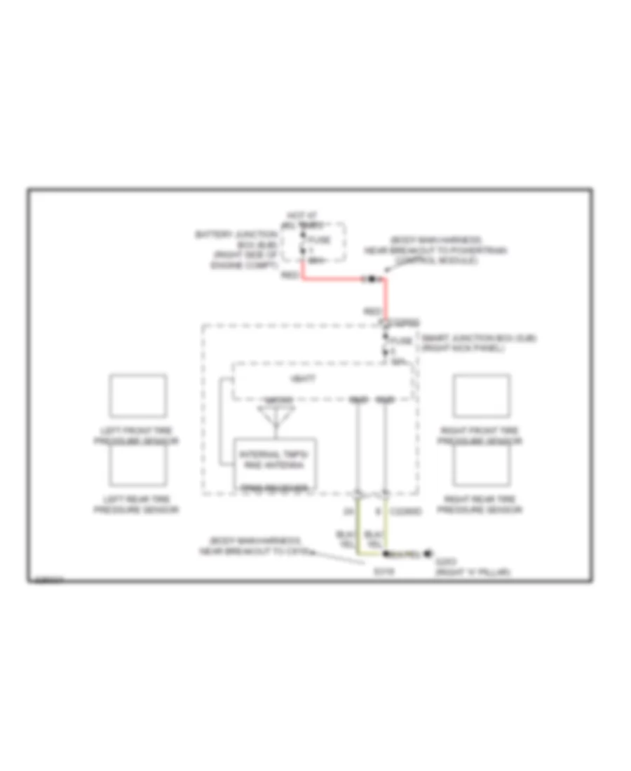
Tire Pressure Monitoring Wiring Diagram for Ford Mustang 2010
List of elements for Tire Pressure Monitoring Wiring Diagram for Ford Mustang 2010:
- (body main harness, near breakout to c919)
- (body main harness, near breakout to powertrain control module)
- Battery junction box (bjb) (right side of engine compt)
- C2280d
- C2280g
- Fuse 10a
- Fuse 80a
- G203 (right "a" pillar)
- Gnd
- Hot at all times
- Internal tmps/ rke antenna
- Left front tire pressure sensor
- Left rear tire pressure sensor
- Micro
- Red
- Right front tire pressure sensor
- Right rear tire pressure sensor
- S114
- S319
- Smart junction box (sjb) (right kick panel)
- Tpms receiver
- Vbatt

 Čeština
 Dansk
Dansk Deutsch
 Ελληνικά
 English
 English
 Suomi
Suomi Français
 Français
 עברית
עברית Hrvatski
 Magyar
 Italiano
 日本語
日本語 한국어
한국어 Nederlands
 Polski
 Português
 Português
 Română
 Русский
 Slovenčina
 Slovenščina
 Svenska
 Türkçe
 中文 (中国)