WARNING SYSTEMS
Chime Wiring Diagram for Honda CR-V LX 2014
 https://portal-diagnostov.com/license.html
Automotive Electricians Portal FZCO
Automotive Electricians Portal FZCO
https://portal-diagnostov.com/license.html
https://portal-diagnostov.com/license.html
Automotive Electricians Portal FZCO
Automotive Electricians Portal FZCO
List of elements for Chime Wiring Diagram for Honda CR-V LX 2014:
- (in right "c" pillar)
- 0) off 1) park 2) auto 3) head
- 5v on/off
- A13
- A20
- A21
- Amp
- B-can transceiver
- B22
- B24
- B29
- B33
- B34
- B40
- Brake fluid level switch (on brake fluid reservoir)
- Brake indicator
- C108
- C116
- Can h
- Can l
- Circuit
- Circuit 5v control
- Circuit dimming
- Combination light switch
- Computer data lines system
- Converter dc/dc
- D11
- D17
- Door indicator
- Driver's door switch (in driver's "b" pillar)
- Driver's junction box 2 (left side of dash)
- Driver's micu
- Driver's seat belt buckle switch (in driver's seat belt buckle assembly)
- Except lx
- Exl
- F-can transceiver
- Fail-safe circuit
- Front passenger's door switch (in front passenger's "b" pillar)
- Front passenger's seat belt buckle switch (in front passenger's seat belt buckle assembly)
- Fuse 10a
- Fuse 7.5a
- G402 (left kick panel)
- G502 (center of dash)
- G601 (under driver's seat)
- G602 (under front passenger's seat)
- Gauge control module
- Headlight switch
- Hot at all times
- Hot in acc or on
- Hot in on or start
- Ignition key switch
- Indicator drive circuit
- Left rear door switch (in left "c" pillar)
- Lights on indicator
- Low oil pressure indicator
- Mixing
- Oil pressure switch (on right front of engine, above oil filter)
- P11
- Parking brake switch (base of parking brake lever assembly)
- Pcm (left side of engine compt)
- Pnk
- Q16
- Red
- Right rear door switch
- Seat belt reminder indicator
- Speaker
- Srs unit (under front of center console)
- Stabilizing 10v
- Tailgate indicator
- Turning-on forced
- Under- dash fuse/ relay box (under left end of dash)
- Under- hood fuse/ relay box (on left side of engine compt)
- W/ res
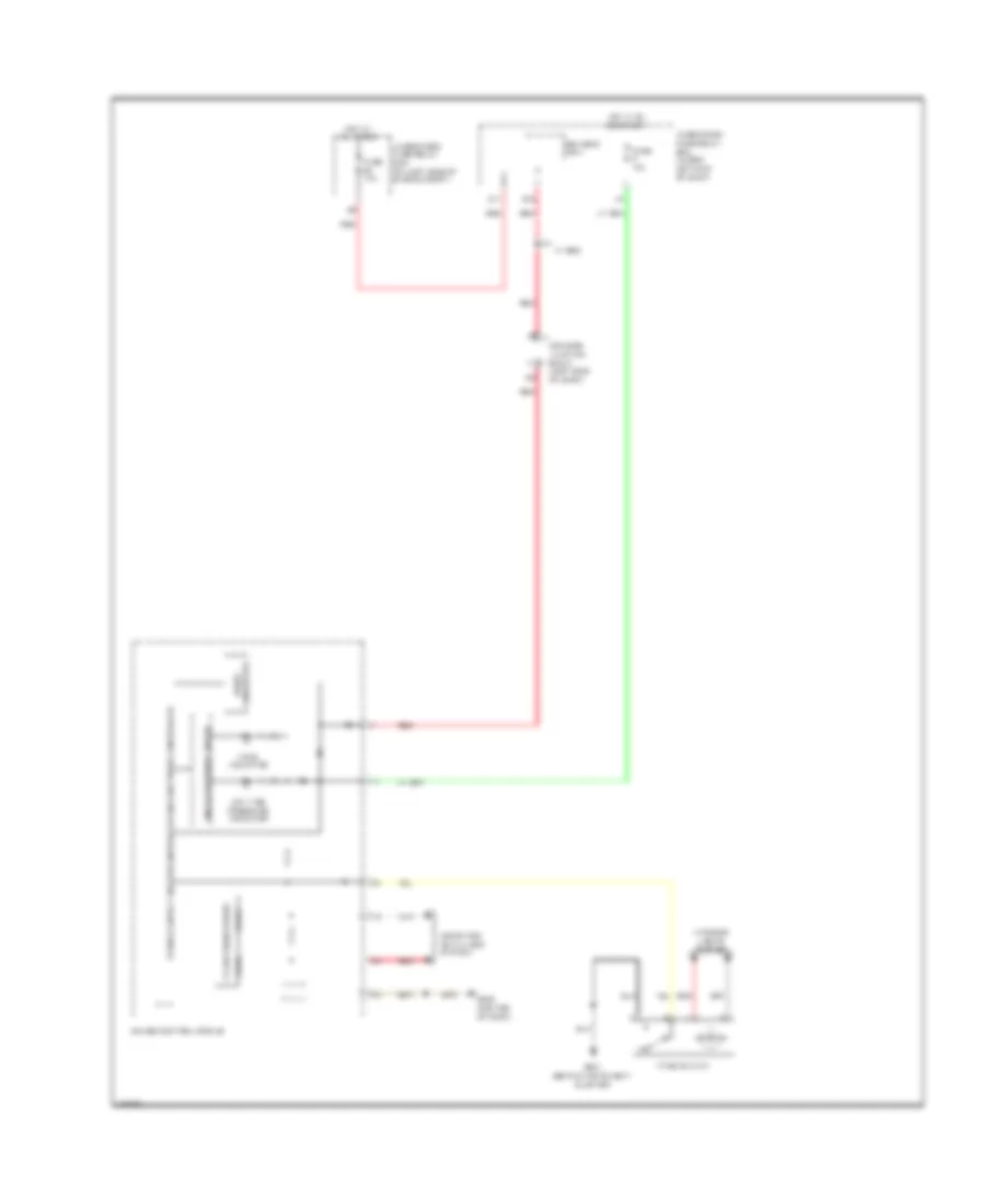
Tire Pressure Monitoring Wiring Diagram for Honda CR-V LX 2014
List of elements for Tire Pressure Monitoring Wiring Diagram for Honda CR-V LX 2014:
- Can h
- Can l
- Computer data lines system
- Converter dc/dc
- D17
- Driver's junction box 2 (left side of dash)
- Driver's micu
- F-can transceiver
- Fuse 10a
- G501 (behind instrument cluster)
- G502 (center of dash)
- Gauge control module
- Hot at all times
- Hot in on or start
- Indicator drive circuit
- Interior lights system
- Low tire pressure indicator
- Q16
- Red
- Tpms indicator
- Tpms switch
- Under-dash fuse/relay box (under left end of dash)
- Under-hood fuse/relay box (on left side of engine compt)
- W/ res

 Čeština
 Dansk
Dansk Deutsch
 Ελληνικά
 English
 Español
 Suomi
Suomi Français
 Français
 עברית
עברית Hrvatski
 Magyar
 Italiano
 日本語
日本語 한국어
한국어 Nederlands
 Polski
 Português
 Português
 Română
 Русский
 Slovenčina
 Slovenščina
 Svenska
 Türkçe
 中文 (中国)