WARNING SYSTEMS
Chime Wiring Diagram for Hyundai Elantra GLS 2012
 https://portal-diagnostov.com/license.html
Automotive Electricians Portal FZCO
Automotive Electricians Portal FZCO
https://portal-diagnostov.com/license.html
https://portal-diagnostov.com/license.html
Automotive Electricians Portal FZCO
Automotive Electricians Portal FZCO
List of elements for Chime Wiring Diagram for Hyundai Elantra GLS 2012:
- Auto
- B-can high
- B-can low
- B-can transceiver
- Bcm (behind center of dash)
- Buzzer
- Computer data lines system
- Door open ind
- Door warning sw
- Driver door switch (on left "b" pillar)
- Driver door switch signal
- Driver seat belt buckle switch
- Driver seat belt switch
- Gf01 (left "b" pillar)
- Gf07 (under center console)
- Gm01 (left top dash panel)
- Head
- High
- Hot at all times
- Hot in on or start
- I/p-c
- I/p-g
- I/p-h
- Ignition key illumination & door warning switch (w/o smart key) (right side of steering column)
- Ill
- Instrument cluster
- Interior lamp fuse 10a
- Ips control module
- Key ill control
- Leak current autocut device
- Light switch
- Low
- M01-l
- M02-a
- M02-b
- M02-c
- Memory fuse 10a
- Micom
- Module 3 fuse 7.5a
- Multifunction switch
- Nca
- Off
- Pnk
- Red
- Seat belt ind
- Smart junction box (under left side of dash, near kick panel)
- Tail
- Tail lamp sw
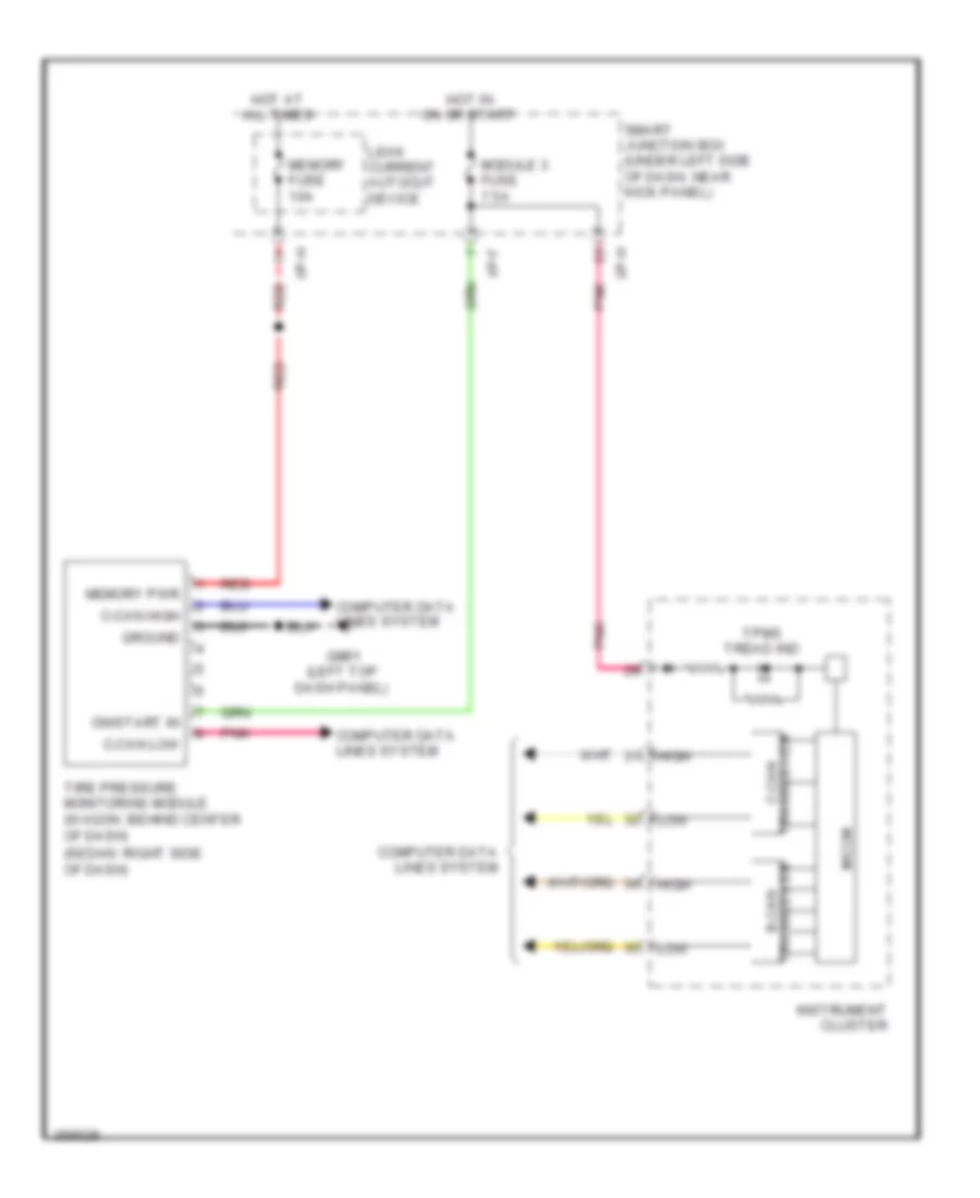
Tire Pressure Monitoring Wiring Diagram for Hyundai Elantra GLS 2012
List of elements for Tire Pressure Monitoring Wiring Diagram for Hyundai Elantra GLS 2012:
- (sedan: right side of dash)
- B-can transceiver
- C-can high
- C-can low
- C-can transceiver
- Computer data lines system
- Gm01 (left top dash panel)
- Ground
- High
- Hot at all times
- Hot in on or start
- I/p-f
- I/p-h
- Instrument cluster
- Leak current autocut device
- Low
- Memory fuse 10a
- Memory pwr
- Micom
- Module 3 fuse 7.5a
- On/start in
- Pnk
- Red
- Smart junction box (under left side of dash, near kick panel)
- Tire pressure monitoring module (wagon: behind center of dash)
- Tpms tread ind

 Čeština
 Dansk
Dansk Deutsch
 Ελληνικά
 English
 Español
 Suomi
Suomi Français
 Français
 עברית
עברית Hrvatski
 Magyar
 Italiano
 日本語
日本語 한국어
한국어 Nederlands
 Polski
 Português
 Português
 Română
 Русский
 Slovenčina
 Slovenščina
 Svenska
 Türkçe
 中文 (中国)