WARNING SYSTEMS
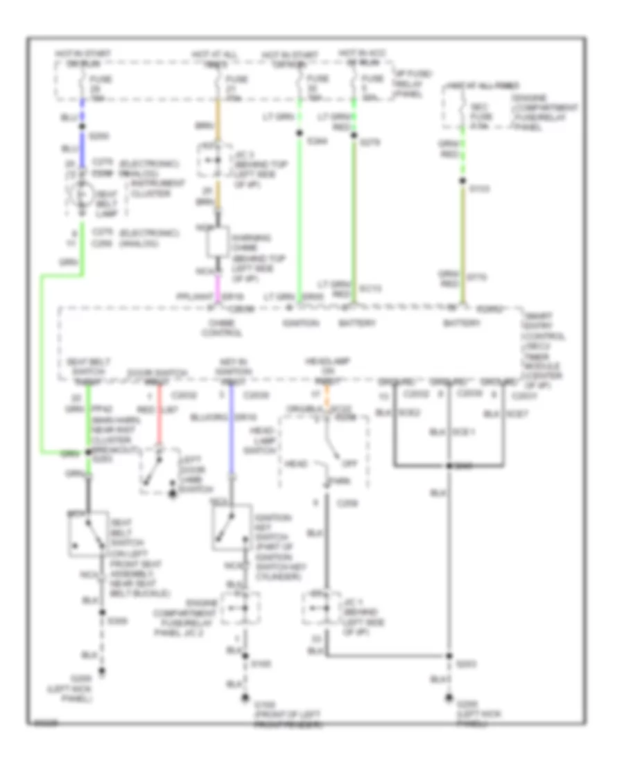
Warning System Wiring Diagrams for Mercury Villager Nautica 1997
List of elements for Warning System Wiring Diagrams for Mercury Villager Nautica 1997:
- (behind top left side of i/p)
- (electronic) (analog)
- (main harn, near inst cluster breakout) s293
- (on left front seat assembly, near seat belt buckle)
- Battery
- C2030
- C2031
- C2032
- C258
- C266
- C268
- C276
- Chime control
- Compartment
- Door switch input
- Engine
- Engine compartment fuse/relay panel
- Fuse 10a
- Fuse 15a
- Fuse/relay
- G100 (front of left front fender)
- G200 (left kick panel)
- Ground
- Head
- Head- lamp switch
- Headlamp on input
- Hot at all times
- Hot in acc of run
- Hot in start or run
- I/p fuse/ relay panel
- Ignition
- Ignition key switch (part of ignition switch key cylinder)
- Instrument cluster
- J/c 1 (behind left side of i/p)
- J/c 3 (behind top left side of i/p)
- Key in ignition input
- Left door jamb switch
- Li87 red
- Nca
- Off
- Panel j/c 2
- Park
- S105
- S133
- S203
- S243
- S244
- S260
- S279
- S300
- Seat belt lamp
- Seat belt switch
- Seat belt switch input
- Sec fuse 7.5a
- Smart entry control (sec)/
- Timer module (center of i/p)
- Warning chime
 Čeština
 Dansk
Dansk Deutsch
 Ελληνικά
 English
 English
 Español
 Suomi
Suomi Français
 Français
 עברית
עברית Hrvatski
 Magyar
 Italiano
 日本語
日本語 한국어
한국어 Nederlands
 Polski
 Português
 Português
 Română
 Slovenčina
 Slovenščina
 Svenska
 Türkçe
 中文 (中国)
 Русский