WARNING SYSTEMS
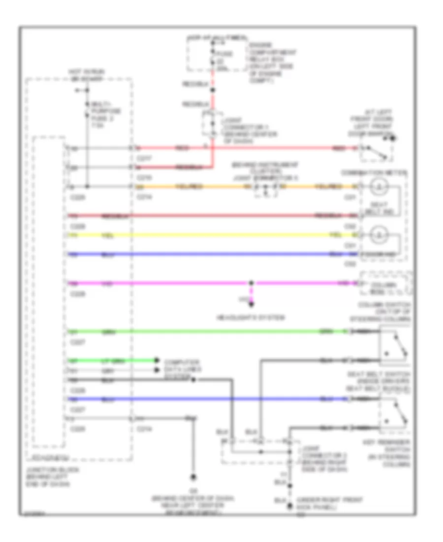
Warning Systems Wiring Diagram for Mitsubishi Lancer ES 2007
List of elements for Warning Systems Wiring Diagram for Mitsubishi Lancer ES 2007:
- (at left front door) left front door switch
- (behind instrument cluster) joint connector 5
- (under right front kick panel) g3
- C01
- C02
- C210
- C214
- C217
- C226
- C227
- C228
- Column ecu
- Column switch (on top of steering column)
- Combination meter
- Computer data lines system
- Door ind
- Engine compartment relay box (on left side of engine compt)
- Etacs-ecu
- Fuse 10a
- G6 (behind center of dash, near left center reinforcement)
- Headlights system
- Hot at all times
- Hot in run or start
- Joint connector 1 (behind center of dash)
- Joint connector 3 (behind right side of dash)
- Junction block (behind left end of dash)
- Key reminder switch (in steering column)
- Multi- purpose fuse 2 7.5a
- Nca
- Red
- Seat belt ind
- Seat belt switch (inside driver's seat belt buckle)
 Čeština
 Dansk
Dansk Deutsch
 Ελληνικά
 English
 Español
 Suomi
Suomi Français
 Français
 עברית
עברית Hrvatski
 Magyar
 Italiano
 日本語
日本語 한국어
한국어 Nederlands
 Polski
 Português
 Português
 Română
 Русский
 Slovenčina
 Slovenščina
 Svenska
 Türkçe
 中文 (中国)
 English